A die cast part can look complete in CAD and still be difficult to fill, eject, or machine. These die casting design guidelines explain how to review the geometry, where numerical starting points help, and which details need agreement before the die is built.
Basic Die Casting Design Requirements
Good die casting design balances part function, metal flow, cooling, and removal from the die. A feature must work in the assembly and survive the manufacturing process.
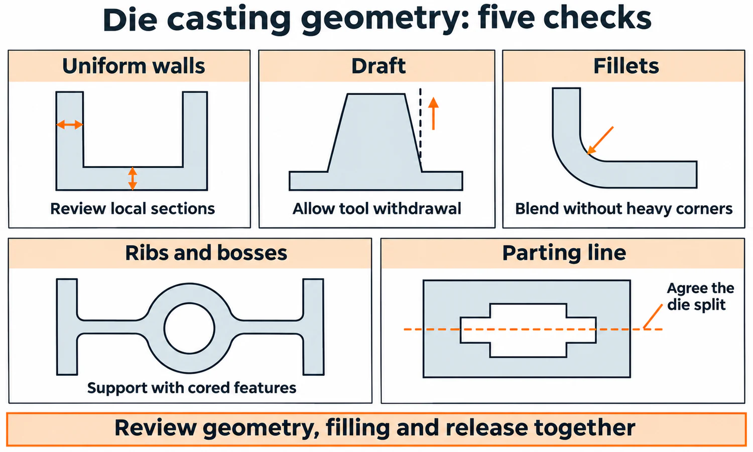
This guide focuses on conventional high pressure die casting of aluminum, zinc, and magnesium. Gravity casting, low pressure casting, and specialized structural casting processes need their own design review. Our guide to the die casting process explains the production sequence behind these requirements.
Use this table for an initial drawing check:
| Design feature | What to check |
|---|---|
| Walls | Consistent sections, gradual transitions, and no unnecessary solid masses |
| Draft | Taper in each withdrawal direction, with functional dimensions preserved |
| Corners | Rounded transitions without creating thick junctions |
| Ribs and bosses | Support where loads require it, with room for filling and release |
| Holes | Core withdrawal, draft, flow around openings, and any finishing operation |
| Parting line | Flash, trimming access, appearance, and dimensional relationships |
| Tolerances | Functional datums and achievable control for each feature |
| Machined surfaces | Enough stock for cleanup without excessive material removal |
| Surface requirements | Agreed cosmetic, sealing, and ejector-mark locations |
Wall Thickness
Keep walls reasonably uniform, then adjust them for load, flow distance, and the selected alloy. Making every wall as thin as possible is not the goal: a thin section still needs to fill reliably and carry its intended load.
Dynacast describes 2 mm, approximately 0.079 in., as a typical aluminum die casting wall thickness, while noting that long parts are harder to cast with very thin walls. Treat this as an early design reference, not a minimum or a guaranteed capability. See its die casting design FAQ.
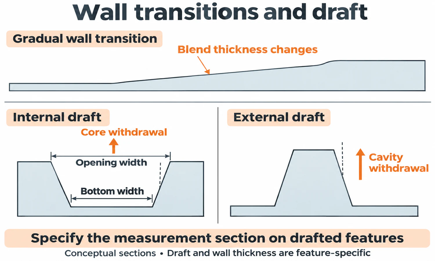
Inspect sections through the model, especially beneath bosses, at corner junctions, and where ribs meet walls. These areas can contain much more metal than the nominal wall dimension suggests.
Where extra thickness is unnecessary, consider a pocket or cored recess. Where a transition is necessary, blend it gradually. The NADCA product design sourcebook, in its geometry guidance, emphasizes consistency without prescribing one universal minimum and maximum wall thickness.
A useful review question is: does this thicker region perform a function, or is it simply material left over from the original CAD shape?
Draft Angles
Draft is the slight taper that helps a casting separate from the die. Apply it to surfaces running along the withdrawal direction, including internal pockets, ribs, and cored features.
Internal and external surfaces behave differently. As metal cools, it can grip the steel forming an internal cavity while shrinking away from the steel around an external wall. That is why the same angle should not automatically be applied everywhere. NADCA’s draft guidance relates the requirement to alloy, feature type, and depth.
Published starting points include:
| Application | Published reference | How to use it |
|---|---|---|
| Aluminum die cast features | Dynacast gives a general achievable range of 1–2° | An initial discussion range; confirm it for each feature |
| Zinc internal surfaces | IZA lists a normal minimum of 1° | Zinc-specific guidance, not a rule for every pocket or rib |
| Zinc external surfaces | IZA lists a normal minimum of 0.5° | Review geometry and release conditions before adopting it |
Sources: Dynacast’s beginner design guide and the International Zinc Association’s design rules.
Check where a drafted dimension is measured. For a hypothetical 20 mm-deep pocket with 1° draft on each side, the width changes by approximately 0.70 mm between its bottom and opening:
Single-side change = 20 × tan(1°) ≈ 0.35 mm.
Two opposing sides = 2 × 0.35 ≈ 0.70 mm, or 0.028 in.
That is enough to affect a mating insert. State which section controls the fit and build the taper around it. This example demonstrates geometry; it does not prescribe 1° for that pocket.
Fillets and Corner Radii
Round sharp internal junctions to reduce stress concentration and improve the transition between features. A fillet is the curved connection between surfaces; an outside radius rounds an exposed corner.
Review both sides of a wall together. Adding a large internal fillet while leaving the outside unchanged can produce a heavy corner. The aim is a smooth transition with sensible local thickness, not the largest radius the CAD tool allows.
For a simple constant-thickness curved wall, the outside radius equals the inside radius plus the wall thickness. That geometric relationship is a useful model check, although actual junctions may need a different arrangement.
Parting edges need separate attention because their shape affects how the die closes and how flash is trimmed. NADCA’s fillet guidance illustrates this distinction rather than rounding every edge indiscriminately.
Ribs and Bosses
Ribs are thin reinforcing walls. Bosses are raised features used for mounting, spacing, or fastening. Both can add useful structure without turning the surrounding area into a solid block.
Ribs
Place ribs where they support the intended load path. Give them draft and blended roots, and review their effect on metal flow. NADCA discusses these functions in its rib design guidance.
Check the complete intersection: several individually thin ribs can meet in one thick node. Also check the spaces between ribs, because the die must contain steel features that form those gaps and release without damage.
There is no useful single rib-to-wall ratio for every die cast part. Rib height, spacing, alloy, filling direction, and stiffness requirements belong in the same review. A ratio copied from a plastic molding checklist is not enough to approve the geometry.
Bosses
Core out a boss where its center does not need to be solid. Use supporting ribs and fillets where required, and provide draft on both its inner and outer surfaces. These are central points in NADCA’s boss guidance.
For example, a screw mounting point needs sufficient material around the hole and a supported load path into the housing. It does not automatically need a solid pedestal extending to the base. Compare a cored boss with local ribs against the solid version, then verify fastening loads and stiffness. This is a design approach, not proof that the lighter version will pass testing.
Holes, Windows, and Threads
Casting a hole can reduce machining, but the hole must suit the tooling and the final fit. Start by identifying the direction in which its core will withdraw.
Holes and windows also interrupt the metal’s path. A large opening may divide the flow, while its perimeter grips the die steel during cooling. NADCA’s holes and windows guidance covers both filling and ejection concerns.
For each hole, define whether it is:
- A clearance hole that can remain as cast.
- A cast pilot that will be drilled, reamed, or tapped.
- A precision bore whose final size and position need machining.
Do not dimension a drafted pilot as though it were a finished cylindrical bore. For a threaded feature, specify the finished thread and required engagement; agree the pilot geometry and finishing route with the die caster. Deep, small holes deserve individual review rather than a universal depth-to-diameter rule.
Parting Lines and Undercuts
The parting line marks where the die halves meet. Decide its position early because it affects feature orientation, flash removal, appearance, and dimensional control. NADCA’s parting-line guidance explains these connections.
Mark sealing faces, visible surfaces, and critical interfaces before agreeing the split. A small seam may be harmless on an internal wall but unacceptable across a gasket contact area.
An undercut prevents a feature from releasing in the main opening direction. It may require a retractable slide, a design change, or a secondary operation.
Compare these options on the finished part. Reorienting a side hole may simplify the die; keeping the hole and using a slide may eliminate repeated drilling. The IZA tooling discussion also explains why sliding cores do not inevitably add significant cycle time. Their value depends on the complete tool and part design.
Tolerances and Datums
Specify tight control where function requires it, and identify the reference features used to measure it. Those reference features are the datums.
A bearing bore’s diameter, its position relative to a mounting face, and the housing’s overall length are different requirements. They should not all receive the same tolerance simply because they appear on one drawing.
Where practical, keep closely related critical features within one die member. Dimensions spanning the die split or independent slides introduce additional relationships to control.
Use an agreed standard and edition when setting general casting tolerances. The NADCA Product Specification Standards cover standard and precision tolerances, coordinate dimensioning, and geometric dimensioning. A statement such as “NADCA tolerances apply” still needs the applicable requirements and drawing exceptions identified.
For initial review, distinguish three groups: features acceptable as cast, features needing specific casting control, and features requiring machining. Confirm the grouping against the actual geometry and production capability before tooling release.
Machining Allowances
Leave enough stock for a machined surface to clean up across expected casting variation, but avoid adding unnecessary material everywhere.
Machining can expose porosity beneath the casting surface. The CWM Design and Specification Guide, in its post-cast machining section, connects stock allowance with casting variation, machining variation, and datum location. It recommends planning these together before die design.
A sealing face therefore needs more than a final roughness callout. Identify the finished plane, surrounding casting geometry, machining references, and the remaining wall after cutting. For a precision bore, review both the amount removed and the final wall around it.
There is no single machining allowance that suits every alloy, dimension, and tool arrangement. Ask for an allowance tied to the feature’s tolerance stack and machining plan.
Gates, Vents, and Ejector Locations
Product designers do not need to calculate the entire gating system, but they should leave suitable locations for it.
Gates admit metal; vents let displaced gas escape; overflows help manage filling. Ejector pins push the solidified casting out. These features can leave attachment or contact marks that need consideration in the product layout.
Mark areas where such marks are acceptable and areas where they would interfere with assembly or appearance. Provide suitable supported regions for ejection instead of expecting a delicate wall to carry the whole release load. Dynacast discusses ejector contact areas in its design for manufacturing FAQ.
Review the resulting arrangement with the die caster. Filling and solidification simulation can help investigate flow paths and hot spots, but tool trials and inspection are still needed to validate production.
Surface Finish and Pressure Tightness
Separate appearance requirements from functional surface requirements. A visible cover, a painted internal bracket, and a gasket face need different acceptance criteria.
Specify which faces are cosmetic, the intended coating or finish, and any areas requiring masking or restricted trimming marks. Avoid using one finish note for the entire part when only selected surfaces need it.
For pressure-tight parts, identify the fluid boundary and machined sealing regions early. Gas porosity and shrinkage porosity can create different problems; uniform walls alone do not eliminate both. Our high pressure die casting guide explains these defects and their relevance to sealing.
Agree test pressure, test medium, acceptable leakage, and inspection stage. Also disclose welding or heat-treatment requirements before choosing the casting route. A part that looks sound externally may still need a different process or additional controls to meet those requirements.
Design Review Before Tooling
Before releasing the die, check the model and drawing together:
- Confirm the alloy, operating conditions, and expected production quantity.
- Identify functional dimensions, datums, and final measurement locations on drafted features.
- Review wall sections, corners, rib intersections, and boss bases.
- Agree die opening direction, parting line, slides, and core withdrawal.
- Mark machining stock, sealing faces, cosmetic zones, and permitted process marks.
- Define dimensional, appearance, and leak-test acceptance where applicable.
- Record the agreed design changes and the revision used for tooling.

If the necessary material or geometry conflicts with the proposed die casting route, revisit process selection before forcing the design to fit. Our investment casting vs. die casting comparison explains where that alternative may be relevant.
Conclusion
Start with consistent walls, suitable draft, rounded transitions, and clearly defined functional surfaces. Then review tooling, tolerances, machining, and inspection together. Tooling release should follow agreement on the dimensions and manufacturing requirements, with the CAD model and drawing updated to match.
FAQs
What Wall Thickness Should I Use for Die Casting?
Dynacast gives 2 mm (about 0.079 in.) as a typical aluminum die casting wall thickness, while noting that long parts are harder to cast with very thin walls. Keep sections reasonably uniform and check thicker regions beneath bosses and at corner junctions—they can contain far more metal than the nominal wall suggests.
How Much Draft Do Die Cast Parts Need?
Published starting points include 1–2° for aluminum features (Dynacast) and minimums of 1° for zinc internal surfaces and 0.5° for zinc external surfaces (IZA). Internal surfaces can grip the die steel as metal cools, so the same angle should not be applied everywhere. Confirm the angle for each feature and check where the drafted dimension is measured.
Can Holes Be Cast Instead of Machined?
Clearance holes can often remain as cast, and cast pilots can be drilled, reamed, or tapped. Precision bores usually need machining for final size and position. Do not dimension a drafted pilot as though it were a finished cylindrical bore.
How Do I Avoid Porosity in Die Cast Parts?
Uniform walls reduce some shrinkage tendencies but do not eliminate all porosity: gas porosity and shrinkage porosity have different mechanisms. For pressure-tight parts, identify the fluid boundary and agree test pressure, medium, acceptable leakage, and inspection stage. Machining can also expose porosity beneath the casting surface.
Where Should the Parting Line Be Placed?
Decide the parting line early with the die caster. It affects flash removal, appearance, and dimensional control, and it should keep closely related critical features within one die member where practical. Mark sealing faces and cosmetic surfaces before agreeing the split.
What Should I Check Before Releasing the Die for Tooling?
Confirm the alloy and production quantity; identify datums and measurement locations on drafted features; review walls, corners, and rib intersections; agree the opening direction and slides; mark machining stock and cosmetic zones; define acceptance criteria; and record the design revision used for tooling.