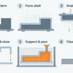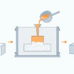
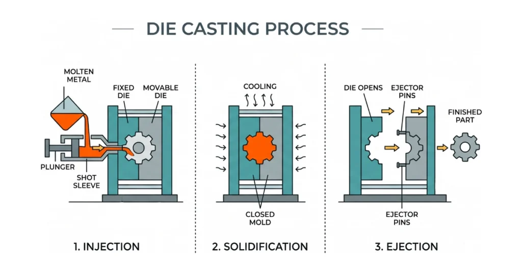
The die casting process turns molten non-ferrous metal into repeatable production parts using a reusable steel die. The actual casting cycle may take place quickly, but a reliable part depends on decisions made much earlier. Material selection, wall thickness, die design, gating, venting, cooling, injection settings, machining allowances, and inspection requirements must work together.
For buyers, understanding this workflow makes it easier to review quotations and identify production risks before tooling begins. This guide explains each process stage, the equipment involved, common defects, and the information a supplier needs to prepare a realistic manufacturing plan.
What Is the Die Casting Process?
Die casting is a permanent-mold manufacturing process in which molten metal enters a reusable steel die and solidifies into the required shape. In conventional high pressure die casting, the machine forces the metal into the cavity at speed and pressure. This allows the alloy to fill thin walls, ribs, bosses, fins, mounting features, and other detailed geometry before it cools.
The process is mainly used for aluminum, zinc, magnesium, and some copper-based alloys. The machine type depends largely on the metal. Zinc is commonly processed using a hot-chamber machine, while aluminum is normally cast using a cold-chamber system.
This page focuses on the manufacturing workflow. The main die casting guide covers the broader subject, including types, materials, applications, advantages, and limitations.
Die Casting Process Diagram
A typical production flow can be shown as:
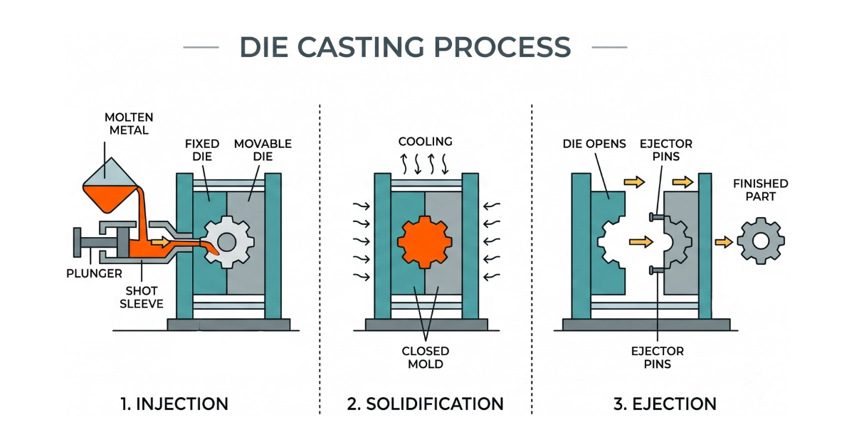
The casting cycle begins at die preparation and ends when the part is ejected. However, tooling development and post-casting operations are also part of the complete manufacturing process. Ignoring these stages can make a quotation appear cheaper than the final delivered part.
Step-by-Step Die Casting Process
1. Drawing Review and DFM Planning
The process begins with the component drawing and 3D model. The foundry reviews the part before designing the die. This design for manufacturability review should identify wall-thickness changes, draft requirements, critical dimensions, parting-line position, undercuts, ejector locations, machining stock, sealing surfaces, and cosmetic areas.
The review should also consider the production quantity and expected tool life. A simple single-cavity die may suit one project, while another may need multiple cavities to reduce cycle cost. Slides, loose inserts, replaceable cores, or complex ejection systems can create necessary features, but they also increase tooling cost and maintenance.
A well-designed part does not apply tight tolerances to every dimension. It separates features that can be produced in the die from those that genuinely need CNC machining.
2. Die Design and Tool Manufacturing
A conventional die has two main halves. The cover half remains fixed to the machine, while the ejector half moves when the casting is released. Together, they form the part cavity.
The die also includes runners and gates that direct the metal, vents that allow displaced air to escape, overflows that collect the first metal entering certain areas, cooling channels that control temperature, and ejector pins that remove the solid casting.
Tool steel selection, heat treatment, machining accuracy, surface condition, and cooling layout all affect die life and part quality. Replaceable inserts are often used around areas that wear quickly or may need adjustment after the first trials.
After assembly, the tool is installed for sampling. The first trial checks filling, ejection, flash, shrinkage, dimensional stability, surface condition, and cycle performance. It is normal to adjust gates, vents, cooling, inserts, or process settings before final tool approval.
The die casting dies and tooling guide explains die structure, tool steel, cavities, slides, maintenance, and ownership in greater detail.
3. Alloy Preparation and Machine Setup
The metal must be prepared under controlled conditions. The supplier checks alloy identification, melt condition, temperature, and cleanliness before casting begins. Recycled runner and gate material may be returned to the process where the alloy specification and quality controls allow it, but composition must remain within the agreed limit.
Machine selection depends on the alloy, projected casting area, part size, shot weight, and required clamping force. A die that is too large for the selected machine creates production and safety problems. A machine that is much larger than necessary may increase cost without improving the part.
The setup stage also establishes die temperature, lubrication method, shot profile, cooling settings, and initial process limits. These settings must later be validated through production trials rather than treated as fixed values copied from another part.
4. Die Lubrication and Clamping
Before injection, the die surfaces are cleaned and sprayed with a controlled release agent. The spray helps the casting separate from the die and also affects thermal balance. Too much lubricant can create gas, surface marks, residue, or unstable die temperature. Too little can contribute to sticking and die soldering.
The machine then closes the die and applies clamping force. The force must resist the pressure created when molten metal fills the cavity. If the die does not remain properly closed, metal may escape at the parting line and create excessive flash.
Stable clamping also protects dimensional repeatability. Worn guide components, poor alignment, debris on the die face, or unsuitable machine settings can affect both flash and part geometry.
5. Metal Transfer and Injection
The injection stage depends on whether the machine uses a hot-chamber or cold-chamber system.
In a hot-chamber machine, the injection mechanism is connected directly to the molten-metal supply. This shortens the transfer route and supports rapid production. It is mainly used with lower-melting alloys such as zinc and some magnesium alloys.
In a cold-chamber machine, metal is melted in a separate furnace and transferred into a cylindrical shot sleeve. A hydraulic plunger then drives the metal through the runner and gates into the die. Aluminum die casting normally uses this route.
Cold-chamber injection is not a single movement. The plunger initially moves more slowly to push the metal through the shot sleeve while limiting air entrainment. It then accelerates during the cavity-filling stage. Additional pressure may be applied after filling to support feeding and compact the metal while it begins to solidify.
The shot sleeve, plunger, runner, gate, vents, and overflows must work as one system. A poor transition from slow shot to fast shot can trap air before the metal even reaches the cavity. This is why the injection profile is developed for the specific tool rather than selected from a general table.
6. Cavity Filling and Pressure Control
During filling, the metal must reach all areas before thin sections freeze. Gate size and position control the direction and speed of flow. Vents and overflows provide routes for air, gases, oxide films, and the first metal front to leave critical areas.
High speed is useful for filling detailed geometry, but uncontrolled turbulence can fold air and oxide films into the casting. The best process is therefore not simply the fastest possible injection. It is a controlled filling pattern suited to the alloy, wall thickness, cavity layout, and venting system.
Vacuum assistance may be used to reduce air pressure inside the cavity before or during filling. This can support lower gas porosity, but it cannot correct poor gate design, leaks, excessive lubricant, or unsuitable shot control.
The high pressure die casting compares conventional, vacuum-assisted, and high-integrity production routes.
7. Cooling and Solidification
Once the cavity is filled, the metal begins transferring heat into the steel die. The machine keeps the die closed while the casting develops enough strength for ejection.
Cooling-channel layout is critical. Thick sections and isolated metal masses cool more slowly than thin walls. If the temperature difference is too large, the casting may develop shrinkage, distortion, hot spots, or longer cycle times.
More cooling is not always better. An excessively cold die can cause incomplete filling or cold shuts, while an overheated area can promote soldering, shrinkage, and dimensional drift. Stable production depends on maintaining a repeatable thermal condition across the die.
Cooling time is often a major part of the total cycle. Increasing it can improve safe ejection but reduces output. Reducing it too far may cause deformation, cracking, or parts sticking to the die. The correct time must be established through trials and production data.
8. Die Opening and Part Ejection
After solidification, the die opens and ejector pins push the casting from the ejector half. The ejected piece is commonly called the shot and may include the finished component, runner, gate, overflows, and flash.
Draft angles help the part release without excessive ejector force. Deep features, rough die surfaces, insufficient draft, local overheating, or die soldering can make ejection difficult. Strong ejector marks or part distortion often indicate that the release system or cooling balance needs attention.
Robots may remove the shot and place it in a cooling station, trimming press, or inspection area. Automation improves cycle consistency, but it still depends on a stable tool and process.
9. Trimming and Post-Casting Operations
The runner, gates, flash, and overflows must be separated from the required component. This may be done using a trim die, saw, press, machining operation, or automated cutting system.
The casting may then need deburring, drilling, milling, turning, tapping, reaming, leak testing, impregnation, heat treatment, shot blasting, polishing, powder coating, painting, plating, or assembly. The correct route depends on the drawing and end use.
Machining should be planned before die design. Extra stock must be provided around bores, sealing faces, and other precision surfaces. Removing too much material can increase cost and may expose internal porosity.
The quotation should make clear whether trimming, CNC machining, surface finishing, inspection, packaging, and assembly are included. The casting price alone may not represent the cost of the finished part.
Main Parts of a Die Casting Machine
The die casting machine provides the clamping force, injection movement, pressure control, and repeatable timing needed for production.
The clamping unit opens and closes the die. The injection unit moves the metal into the cavity. In a cold-chamber system, the shot sleeve receives molten metal and guides the plunger. In a hot-chamber system, the injection mechanism works directly with the furnace.
Modern machines also control shot position, velocity, pressure, die spray, cooling, cycle timing, and safety interlocks. However, advanced equipment cannot compensate for a poor part design or an unsuitable die. Machine, tool, alloy, and process settings must be developed together.
Out die casting machine page examines clamping systems, shot units, machine size, automation, and the relationship between projected area and clamping force.
Hot-Chamber vs Cold-Chamber Die Casting
| Factor | Hot Chamber | Cold Chamber |
| Metal supply | Injection system connected to the melt | Metal transferred from a separate furnace |
| Common alloys | Zinc and some magnesium alloys | Aluminum, magnesium, and some copper-based alloys |
| Cycle | Usually faster | Additional metal-transfer step |
| Main concern | Compatibility with submerged components | Transfer control and air in the shot sleeve |
| Typical use | Smaller detailed parts | Aluminum housings and larger industrial components |
The names describe the injection system, not whether the molten metal itself is hot or cold. Both processes use molten alloy. The distinction is how the metal reaches the injection mechanism.
How Process Control Affects Casting Quality
Reliable die casting depends on a controlled process window. The operator and process engineer must monitor several variables together rather than adjust one setting in isolation.
Metal temperature affects flow and solidification. Die temperature influences filling, surface condition, soldering, cycle time, and dimensional stability. Shot velocity and transition position affect air entrapment. Injection pressure influences filling and feeding. Lubrication affects release and gas generation. Cooling controls the local solidification pattern.
The objective is not to maximize every parameter. It is to keep the full process stable. A higher temperature may improve filling but increase soldering or cycle time. More lubricant may improve release but create gas or residue. Faster injection may fill a thin wall while increasing turbulence elsewhere.
This is why production records, first-article inspection, cavity-to-cavity comparisons, and defect trends are important. They help distinguish a random defect from a process shift.
Common Die Casting Process Defects
Gas porosity develops when air or gases become trapped during filling. Venting, vacuum, lubricant control, shot-sleeve filling, and injection settings all affect this risk.
Shrinkage porosity forms where the metal cannot compensate for volume contraction during solidification. Heavy sections, isolated hot spots, and poor cooling balance are common contributors.
Cold shuts and misruns occur when metal fronts do not join correctly or the cavity does not fill completely. Low metal or die temperature, poor flow paths, and slow filling can contribute.
Flash appears when metal escapes between die surfaces or around moving components. It may indicate die wear, poor alignment, debris, insufficient clamping, or excessive pressure.
Soldering occurs when the casting alloy sticks to the die surface. Local overheating, die condition, alloy chemistry, and lubrication can all influence it.
Defects should not be treated only as inspection problems. The cause must be traced back to the part, die, machine, metal, or process setting.
Die Casting Process Quality Control
Quality control starts with an approved drawing and process plan. First-article inspection confirms that dimensions, appearance, machining, and functional requirements can be achieved before full production.
Dimensional checks may use gauges, fixtures, calipers, or coordinate measuring machines. Material verification may include chemical analysis and certificates. X-ray inspection can help evaluate internal porosity, while leak testing is useful for pressure-tight housings. Surface finishes, coatings, threads, and machined features need their own acceptance criteria.
The NADCA technical standards provide guidance on tooling, alloys, tolerances, design, and quality assurance for die castings. General casting tolerances and machining allowances can also be referenced through ISO 8062-3:2023. For aluminum-alloy die castings, ASTM B85/B85M provides material specification requirements.
A standard reference should not replace a clear drawing. Critical dimensions, testing, sampling, documentation, and acceptance limits should be agreed before production.
What Affects Die Casting Cycle Time and Cost?
Tool complexity has a major effect on both investment and production cost. Multiple cavities may reduce the unit cost but increase the tool size and initial expense. Slides, inserts, complex cooling, difficult ejection, and tight tolerances also add cost.
The production cycle depends on metal transfer, injection, cooling, die opening, ejection, lubrication, and part removal. Cooling is often the longest stage. A larger or heavier part generally needs more time before safe ejection.
Unit cost is also affected by alloy price, casting weight, runner and overflow percentage, scrap, machine size, cavity count, machining, finishing, inspection, packaging, maintenance, and annual volume.
Two quotations are only comparable if they include the same scope. Tool ownership, trial samples, engineering changes, maintenance responsibility, machining, coating, inspection reports, and shipping should be stated separately.
What Buyers Should Include in a Die Casting RFQ
| RFQ information | Why it matters |
| 3D CAD model and controlled 2D drawing | Defines geometry, dimensions, GD&T, and revisions |
| Alloy or functional material requirement | Guides machine, process, finishing, and quality planning |
| Annual volume and batch size | Determines cavity count, automation, and tooling economics |
| Critical dimensions and surfaces | Prevents unnecessary tolerance and inspection cost |
| Machining and finishing requirements | Allows correct stock, fixturing, and process planning |
| Leak, strength, cosmetic, or safety requirements | Defines defect limits and inspection methods |
| Target life and tool ownership terms | Clarifies die construction, maintenance, and replacement |
| Packaging and destination | Protects finished surfaces and supports logistics planning |
YTD Foundry can use this information to review the design before tooling begins and identify where changes could improve filling, ejection, quality, or total manufacturing cost.
Conclusion
The die casting process is more than injecting molten metal into a steel die. A reliable part depends on the connection between design, tooling, machine selection, filling, cooling, ejection, finishing, and inspection.
Buyers can reduce cost and quality risk by involving the foundry before tooling approval. A complete drawing, realistic tolerances, clear functional requirements, and an agreed inspection plan allow the process to be designed around the finished part rather than corrected after production begins.
FAQs
What are the main steps in the die casting process?
The complete workflow includes DFM review, die design, tool manufacturing, die preparation, metal injection, cooling, ejection, trimming, secondary operations, and inspection.
What is a shot sleeve in die casting?
A shot sleeve is the cylindrical chamber used in a cold-chamber machine. Molten metal is transferred into it, and a plunger pushes the metal through the runner and gates into the die.
Why is aluminum normally cold-chamber die cast?
Aluminum is melted in a separate furnace because its temperature and chemical behavior are unsuitable for most conventional submerged hot-chamber injection systems.
How long does a die casting cycle take?
Cycle time depends on the alloy, casting size, wall thickness, cavity count, cooling system, machine, and automation. A supplier should estimate it from the actual tool and part rather than use a universal value.
Can die cast parts be CNC machined?
Yes. Machining is commonly used for sealing faces, bearing bores, threads, and tightly controlled dimensions. Machining stock and porosity risk should be considered during die design.
What causes porosity during the die casting process?
Gas porosity is linked to trapped air, gases, lubrication, and filling behavior. Shrinkage porosity is linked to solidification and hot spots. Each requires a different corrective action.