Choosing a casting process is not a matter of ranking methods from “basic” to “advanced.” Each mold system solves a different manufacturing problem.
For the six processes compared here—silica-sol investment casting, water-glass investment casting, die casting, lost foam casting, shell mold casting, and clay-bonded sand casting—the fastest way to narrow the choice is to look at material, part size, geometry, required as-cast quality, lifetime volume, and finished-part cost.
Casting Process Comparison: Quick Overview
| Process | Typical Material Fit | Accuracy / Surface Reference | Tooling Commitment | Best Fit |
|---|---|---|---|---|
| Silica-Sol Investment Casting | Steel, stainless, superalloys, selected non-ferrous alloys | YTD: ±0.15 mm up to 25 mm; ±0.20–0.30 mm at 25–100 mm. Typical silica-sol surface: Ra 1.6–3.2 μm | Medium | Complex precision parts with limited machining |
| Water-Glass Investment Casting | Mainly steel and other suitable ferrous alloys | Typical surface reference: Ra 6.3–12.5 μm | Low–Medium | Cost-sensitive steel parts needing lost-wax geometry |
| Die Casting | Aluminum, zinc, magnesium | YTD network: about ±0.05 mm hot chamber; ±0.10 mm cold chamber / vacuum die casting | Very High | Stable, high-volume thin-wall non-ferrous parts |
| Lost Foam Casting | Commonly cast iron and aluminum | AFS reference: about 0.002 in/in plus foam-pattern tolerance in a controlled process | Low–Medium to High, depending on pattern production | Complex consolidated shapes without conventional parting lines |
| Shell Mold Casting | Ferrous and non-ferrous alloys | YTD: CT6–CT9; Ra 3.2–12.5 μm | Medium | Small and medium repeat parts needing better sand-casting precision |
| Clay-Bonded Sand Casting | Very broad alloy range, especially cast iron | YTD: CT10–CT13; Ra 12.5–50 μm | Low | Large parts, broad materials, modest tooling investment |
These figures are useful reference points rather than interchangeable guarantees. Part size, geometry, alloy, tooling, mold control, and inspection requirements still determine what can be held on a specific drawing.
For example, an Investment Casting Institute design reference gives a practical investment-casting tolerance range of roughly ±0.003–0.005 in per inch, while a Steel Founders’ Society of America production example reports ±0.008 in across a 1 in dimension for shell molding and ±0.030 in for green sand. The SFSA example also notes that actual foundry capability can vary significantly.
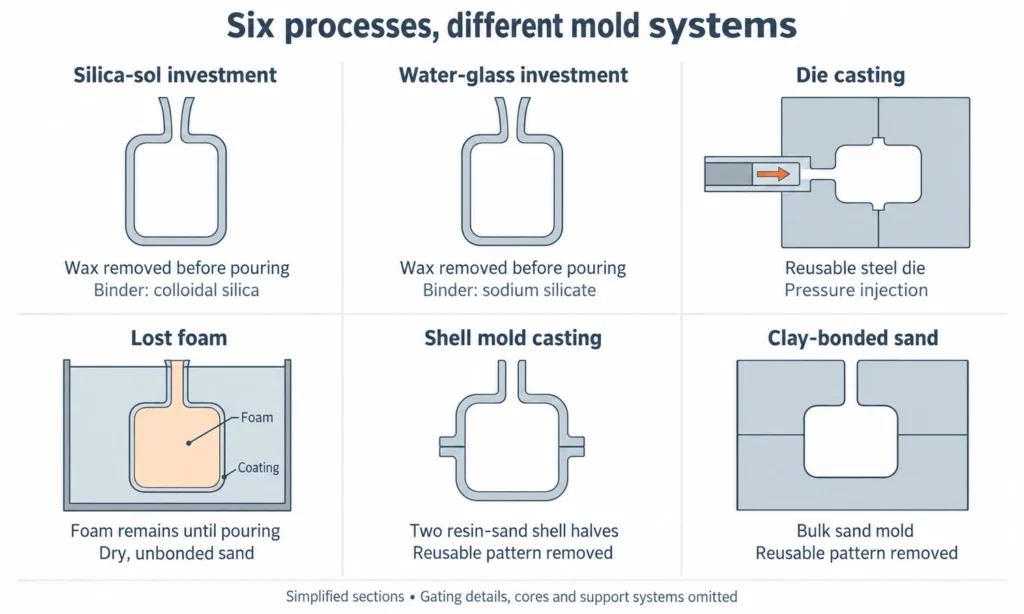
Mold and Pattern Systems Used by the Six Casting Processes
The six processes become easier to compare once the mold system is clear.
Silica-Sol and Water-Glass Investment Casting
Both are investment casting processes.
A reusable tool normally creates wax patterns. Those patterns are assembled and covered with refractory ceramic. After the wax is removed, molten metal fills the expendable ceramic shell.
The distinction is the shell binder.
Silica sol uses colloidal silica, while water glass uses sodium silicate. This changes how the shell develops strength and influences the balance between process cost, surface reproduction, dimensional control, and shell production.
Our Silica Sol vs Water Glass Casting guide goes deeper into that comparison.
Die Casting
Die casting sends molten metal directly into a reusable steel die under high pressure.
The die contains not only the part cavity but also gating, venting, cooling, ejection, and any slides or moving cores required by the geometry.
The high permanent-tooling investment is what later allows very fast repeated production.
The 2024 NADCA Product Specification Standards for Die Castings covers tooling, alloy data, standard and precision tolerances, GD&T, quality requirements, and die-casting design guidance.
Lost Foam Casting
Lost foam uses an expendable foam replica of the component.
The coated foam pattern stays inside dry, unbonded sand. Molten metal decomposes the foam and progressively replaces its volume.
Because the pattern is not withdrawn from the mold, conventional parting-line and draft restrictions can be reduced substantially.
Shell Mold Casting
Shell molding uses resin-coated sand and a heated reusable pattern.
The heated pattern cures a thin rigid sand shell. Two shell halves are assembled to create the expendable mold.
The mold is still sand, but the rigid shell and dedicated tooling give the process better repeatability and surface reproduction than conventional clay-bonded sand.
Clay-Bonded Sand Casting
Clay-bonded sand, commonly called green sand, uses sand, clay, water, and additives to form the mold around a reusable pattern.
“Green” refers to the mold being used in a moist, uncured state—not to its color.
It is one of the most flexible processes in this comparison for part size, alloy range, and tooling investment.

Material Compatibility Across the Six Casting Processes
Material is usually the first filter.
If the drawing specifies stainless steel, carbon steel, alloy steel, or a nickel-based superalloy, conventional high-pressure die casting normally leaves the shortlist. Its reusable steel die is much better suited to lower-melting non-ferrous alloys such as aluminum, zinc, and magnesium.
Silica-sol investment casting is particularly relevant when those higher-melting alloys also need complex geometry, good surface reproduction, or limited machining.
Water-glass investment casting serves a similar material range for many steel parts but is more often selected when cost has greater weight than achieving the finer shell quality associated with silica sol.
Cast iron points naturally toward the sand-based processes. Clay-bonded sand is widely used for gray and ductile iron, while shell molding can improve dimensional repeatability on smaller repeated iron castings.
Lost foam is also well established for cast iron and aluminum, particularly where one foam pattern can replace a more complicated conventional mold-and-core assembly.
So material can narrow the field quickly:
- Steel / stainless / superalloy → investment casting or sand-based routes
- Cast iron → clay sand, shell mold, or lost foam
- Aluminum → die casting, sand processes, lost foam, and selected investment-casting routes remain possible
- Zinc / magnesium at high volume → die casting moves strongly to the front
Part Size and Weight
Part size often removes another group of processes.
Clay-bonded sand has the broadest large-part range among these six methods. YTD’s current sand-casting network lists green-sand capability from roughly 0.5 kg up to 5,000 kg, with much larger dimensions than the precision processes.
Shell molding occupies a smaller range. Our current network lists shell-mold castings at approximately 0.1–100 kg, with a maximum envelope around 800 × 800 × 500 mm.
Silica-sol investment casting is strongest for small and medium precision parts, although much larger castings are possible. Our current in-house capability lists a maximum envelope up to 600 × 800 × 800 mm for suitable iron-based and aluminum alloys, with practical feasibility still determined by the complete tree and pour weight.
Die casting size is tied to shot capacity, die size, and machine clamping force. Our current partner capability covers parts up to roughly 20 kg for cold-chamber and vacuum die casting.
Lost foam can move much further into large-part territory because the expendable foam pattern is supported by sand and does not require conventional mold withdrawal.
A large iron housing and a 200-gram aluminum enclosure therefore belong in very different process discussions before surface finish is even considered.
Parting Lines, Internal Cavities, and Complex Geometry
Geometry separates the processes in a different way.
Silica-Sol Investment Casting
Investment casting does not need to release the final metal part from a reusable metal die.
The ceramic shell is broken away after casting, and sacrificial ceramic cores can form selected internal passages.
This makes silica-sol investment casting especially useful for complex three-dimensional external geometry and internal features without a simple mechanical pull direction.
Water-Glass Investment Casting
Water-glass investment casting has the same basic lost-wax geometry freedom.
The decision between silica sol and water glass is therefore usually driven more by required casting quality and cost than by a fundamental difference in what shape the wax process can create.
Die Casting
Die casting can produce highly complex parts, but the solid casting must leave the reusable die.
Draft, parting lines, core-pull directions, ejector access, and slides all affect the tool.
A side hole can be created with a moving core. An undercut can use a slide. But every additional movement increases tooling cost and mechanical complexity.
Our Investment Casting Mold vs Die Casting Mold guide explains this tooling difference in more detail.
Clay-Bonded Sand and Shell Molding
Both normally remove a reusable pattern before pouring, so parting lines and pattern withdrawal still matter.
Internal cavities are commonly produced with expendable sand cores.
Shell molding gives better mold consistency, but it does not remove the basic need to design the pattern and cores so the mold can be assembled reliably.
Lost Foam Casting
Lost foam removes the pattern-withdrawal problem because the foam stays inside the mold until pouring.
Several foam sections can also be assembled into a single pattern.
This can reduce conventional cores, mold joints, and parting lines for components that would otherwise require a complicated sand-mold assembly.
The tradeoff is that foam density, pattern accuracy, coating permeability, sand packing, and decomposition gases become important process variables.
Dimensional Accuracy, Surface Finish, and Machining
This is where numerical comparisons help most—but only when the measurement method and process condition are clear.
For silica-sol investment casting, YTD’s current process data shows typical as-cast tolerances of about ±0.15 mm for dimensions up to 25 mm, ±0.20–0.30 mm for 25–100 mm, and ±0.30–0.50 mm for 100–200 mm.
A broader Investment Casting Institute reference gives practical dimensional capability around ±0.003–0.005 in/in and as-cast surface finish of roughly 40–125 microinches RMS. See the ICI investment-casting design reference.
RMS and Ra should not be treated as interchangeable values. The Investment Casting Institute’s 2024 technical paper on surface inspection specifically warns that surface parameters and measurement methods need to be identified correctly.
For YTD’s two investment-shell routes, our current process reference is:
- Silica sol: typically Ra 1.6–3.2 μm
- Water glass: typically Ra 6.3–12.5 μm
These figures explain why silica sol becomes more attractive when a larger percentage of the finished component needs to remain as cast.
For sand-based processes, our current network reference is:
- Shell molding: CT6–CT9, Ra 3.2–12.5 μm
- Clay / green sand: CT10–CT13, Ra 12.5–50 μm
A useful independent comparison comes from the SFSA steel-casting design study. In that specific production example, shell molding achieved about ±0.008 in across a 1 in dimension, while green sand was about ±0.030 in. Nominal finishes were approximately 300–500 RMS for shell mold and 500–900 RMS for green sand.
Lost foam sits differently because the foam pattern itself becomes part of the dimensional chain. An AFS lost-foam design webinar gives a reference capability of approximately 0.002 in/in plus the machined-foam tolerance for a controlled lost-foam process.
For die casting, our current partner capability uses approximately ±0.05 mm as a hot-chamber reference and ±0.10 mm for cold-chamber and vacuum die casting. The exact drawing should still be checked against the applicable NADCA standard or foundry capability rather than applying one tolerance to all features.
The manufacturing decision is not simply “which casting is most accurate?”
If a sealing face, precision bore, and mounting datum will all be CNC machined anyway, paying for the finest possible as-cast condition across the whole component may not reduce finished cost.
If most of the product needs to remain as cast, the precision of the mold system has much more economic value.
Tooling Commitment, Design Changes, and Lifetime Production Volume
The six processes put very different amounts of money into permanent tooling.
Clay-bonded sand usually has the lowest conventional tooling barrier. Patterns can be relatively straightforward, which also makes design changes easier to accommodate.
Lost foam can start with machined or otherwise low-tooling foam patterns for development. At repeat production volume, dedicated foam-pattern tooling becomes more important.
Silica-sol and water-glass investment casting normally use reusable wax tooling, but prototypes can sometimes bypass that tooling with printed sacrificial patterns.
Shell molding needs durable heated tooling to make repeatable resin-sand shells, placing it above conventional green sand in tooling commitment.
Die casting has the highest permanent-tooling commitment. The steel die may include cavities, slides, cooling circuits, ejectors, inserts, gating, and venting.
That also changes the cost of design revisions.
Moving a boss or changing a local feature on a sand-casting pattern or investment-casting wax tool can sometimes be handled with a localized tooling modification.
The same change in a die-cast component may affect hardened die steel, inserts, shut-offs, ejectors, slides, or cooling passages.
Lifetime production therefore matters more than the first purchase order.
NADCA notes that suitable die casting tooling can produce hundreds of thousands of identical parts before additional tooling is required. That is exactly why an expensive die can make economic sense for a stable long-running program.
There is no equally useful universal “minimum quantity” at which die casting becomes cheaper. Tool complexity and the machining avoided by the casting can move the break-even point dramatically.
Finished-Part Cost vs. Raw Casting Cost
A casting quotation only tells part of the manufacturing story.
Consider two processes for the same housing.
Process A produces a cheaper blank but leaves rougher sealing faces, wider bore variation, and more machining stock.
Process B costs more at the foundry but leaves the exterior, bosses, lettering, and several interfaces acceptable as cast.
The lower casting price does not automatically produce the lower finished cost.
The complete comparison should include:
tooling + casting + heat treatment + machining + finishing + inspection + expected scrap / rework
This is especially important when comparing silica-sol investment casting with lower-cost sand or water-glass routes.
The value of a finer casting process comes from the operations it actually removes.
If every important surface will be machined regardless, paying for tighter as-cast control may add little.
If a more precise mold eliminates several setups, grinding operations, or finishing steps, the higher casting price can be economically justified.
Typical Project Fit for Each Casting Process
Silica-Sol Investment Casting
Evaluate silica sol when the part combines steel, stainless steel, or a suitable superalloy with complex geometry, relatively tight as-cast dimensions, and surfaces that benefit from remaining near net shape.
It is our core in-house casting process at YTD. See our Investment Casting Service for current capabilities.
Water-Glass Investment Casting
Evaluate water glass when lost-wax geometry is useful but the part can accept a coarser surface and less demanding dimensional performance in exchange for a lower-cost shell route.
It is especially relevant to cost-sensitive ferrous parts that would otherwise require more complicated sand cores or additional machining.
Die Casting
Evaluate die casting when the alloy is aluminum, zinc, or magnesium, the design is stable, and lifetime production is large enough to justify the steel die.
It has a particular advantage for thin walls, repeated fine features, and rapid automated production.
See our Die Casting Service for the partner-supported processes available through YTD.
Lost Foam Casting
Evaluate lost foam when eliminating conventional parting lines, reducing core assembly, or consolidating several pieces into one casting creates significant value.
The process is especially relevant to complex cast-iron and aluminum components.
Shell Mold Casting
Evaluate shell molding for small and medium repeat parts that need better as-cast consistency than ordinary clay-bonded sand but do not justify investment casting.
Its metal tooling and rigid resin-sand shells make it especially suitable for repeat production.
Clay-Bonded Sand Casting
Evaluate clay-bonded sand when part size, broad material choice, and moderate tooling investment matter more than the finest as-cast surface.
For large gray- and ductile-iron housings, machine structures, and general industrial castings, it remains one of the most practical manufacturing routes.
Our Sand Casting Service compares YTD’s current green-sand and shell-mold partner capabilities.
A Practical Order for Choosing a Casting Process
When we review a drawing, comparing all six processes equally from the beginning usually wastes time. A fixed sequence narrows the field much faster.
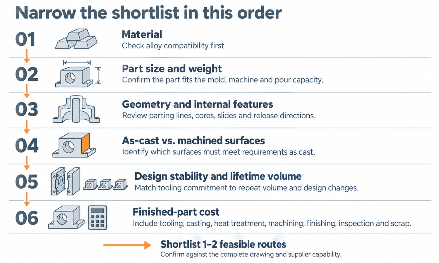
1. Material
Start with the alloy.
High-melting steels and superalloys eliminate conventional die casting. Zinc immediately makes die casting much more relevant. Cast iron moves the decision toward the sand-based processes.
2. Part Size and Weight
Next, remove processes that do not fit the physical scale.
A multi-ton iron housing belongs in clay-bonded sand or another large sand-based route. A small precision stainless bracket belongs in a completely different part of the process map.
3. Geometry and Internal Features
Check parting lines, undercuts, internal passages, and the number of cores or tool movements required.
Ceramic cores, sand cores, die slides, and expendable foam patterns solve different geometric problems.
4. As-Cast vs. Machined Surfaces
Mark which dimensions actually need to come from the casting.
If most critical interfaces will be machined, there is less value in purchasing the highest as-cast precision everywhere.
If logos, curved surfaces, thin features, and multiple interfaces must remain as cast, precision becomes much more valuable.
5. Design Stability and Lifetime Volume
A high permanent-tooling investment makes sense only when the design is stable enough to use it.
Prototype quantities or regularly changing geometry favor lower tooling commitment.
Stable high-volume production can justify shell tooling, automated foam-pattern tooling, or a sophisticated die casting die.
6. Finished-Part Cost
Finally, compare the component after all required work is complete.
The process with the lowest raw casting price may lose once machining, finishing, inspection, scrap, and tooling are added.
This six-step sequence usually reduces the original list to one or two realistic processes.
How We Route Casting Projects at YTD
At YTD, silica-sol investment casting is our core in-house casting process.
Tooling, wax patterns, shell building, investment casting, heat treatment, CNC machining, standard blasting and polishing, inspection, reverse engineering, and suitable casting simulation can be integrated within that workflow.
The other processes in this comparison are provided through specialized production partners when they fit the part better. These include water-glass investment casting, die casting, lost foam casting, shell mold casting, and clay-bonded sand casting.
That matters because process selection should start from the drawing rather than from whichever production line happens to be in-house.
A stainless-steel precision component may stay within our silica-sol investment-casting workflow. A large ductile-iron housing may move to clay-bonded sand. A complex cast-iron component with difficult parting lines may benefit from lost foam. A stable thin-wall aluminum housing produced in large quantities may belong in die casting.
The part determines the route.
Final Thoughts
The six casting processes are easier to compare when they are treated as different mold systems rather than as a ranking from cheap to expensive or rough to precise.
Start with the alloy and physical size, then compare geometry, the surfaces that must remain as cast, design stability, lifetime volume, and finished-part cost.
That sequence usually shows where each process earns its place—and prevents paying for casting capability the finished component does not actually need.
FAQs
Which Casting Process Has the Best Surface Finish?
Among these six processes, silica-sol investment casting and die casting generally provide the finest as-cast surfaces. YTD’s silica-sol reference is typically Ra 1.6–3.2 μm, while shell molding is typically Ra 3.2–12.5 μm and clay-bonded sand Ra 12.5–50 μm within our current network.
Which Casting Process Has the Lowest Tooling Cost?
Clay-bonded sand usually has the lowest conventional permanent-tooling commitment. Investment casting and lost foam can also reduce tooling for prototypes by using printed or machined expendable patterns. Die casting normally requires the largest permanent-tooling investment.
Which Process Is Best for Large Castings?
Among these six processes, clay-bonded sand has the broadest large-part capability. Lost foam is also useful for relatively large parts when geometry or part consolidation makes conventional mold assembly difficult.
Which Process Is Best for Stainless Steel?
Silica-sol investment casting is a strong choice for complex precision stainless-steel parts. Sand casting becomes more relevant as size increases and as-cast precision becomes less important.
Which Process Is Best for High-Volume Aluminum Parts?
Die casting is usually the first process to evaluate for a stable high-volume aluminum design, especially when thin walls, fast cycles, and repeatability matter.
What Is the Difference Between Shell Mold Casting and Investment Casting?
Shell molding creates expendable resin-sand mold halves on reusable tooling. Investment casting creates a ceramic shell around a sacrificial pattern. The different mold systems give investment casting greater freedom from conventional parting lines, while shell molding can provide an economical precision sand-casting route for repeated parts.