What is lost foam casting
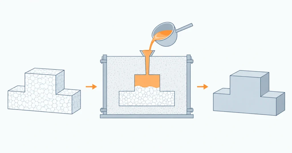
Lost foam casting is a metal casting process in which a disposable foam replica of a part stays inside the mold during pouring. Heat from the molten metal breaks down the foam, and the metal progressively takes its place. After the metal solidifies and the surrounding sand is removed, the casting retains the shape of the original replica.
Leaving the pattern in place makes complex shapes easier to mold. Internal passages and features that would complicate a conventional sand mold can sometimes be cast together in one piece. The challenge is that the foam must decompose and its byproducts must escape while the metal fills the shape. Understanding that balance explains both the process’s advantages and its limitations.
How the lost foam casting process works
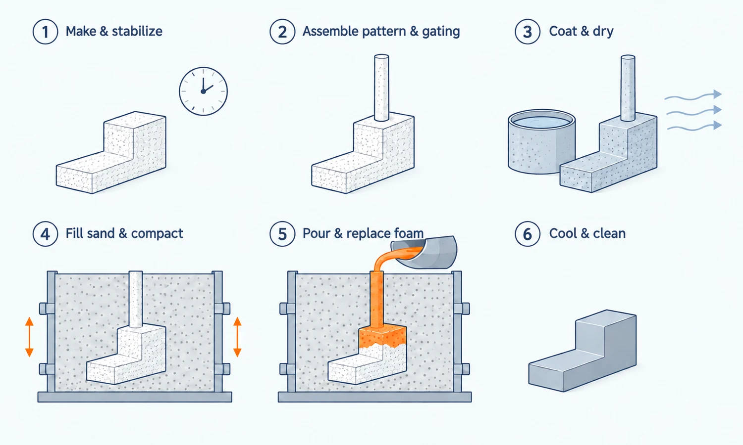
A typical lost foam mold has three main elements: a foam pattern that defines the metal part, a heat-resistant coating around the pattern, and dry sand that supports it. The sand is normally unbonded, meaning it has no binder holding its grains together.
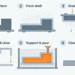
The production sequence turns these materials into a supported shape that the metal can replace.
- Make a lightweight polymer model of the casting. The process begins with a foam pattern that reproduces the intended casting geometry. For repeat production, expanded polystyrene (EPS) beads are commonly fused together with steam in a dedicated mold. The pattern is allowed to stabilize before use because its dimensions can continue changing after molding.
- Assemble the pattern and metal delivery system. Complex shapes may be made as several foam sections and joined together. Foam channels are then attached to provide the paths through which metal will enter. One or more part patterns and their connecting channels form a cluster. Alignment and adhesive application matter: a misplaced section or excessive glue can affect the finished casting.
- Coat and dry the assembly. A refractory, or heat-resistant, coating covers the foam. It separates the metal from the sand and allows decomposition products to move away from the advancing metal. The coating must dry thoroughly and uniformly before molding.
- Pack the assembly in sand. The coated pattern is placed in a container called a flask. Dry sand is added and compacted by controlled vibration, including inside accessible passages. This supports the pattern and coating during pouring. Poor compaction can leave unsupported areas; excessive or unsuitable vibration can distort the foam.
- Pour, cool, and finish. Molten metal enters the assembly and progressively replaces the foam. Once the casting has solidified and cooled sufficiently, the loose sand is removed. The metal delivery channels are cut off, and the part is cleaned, inspected, and machined where required.
The foam is not pulled out or burned out before pouring in this standard process. That distinguishes lost foam casting from methods that first create an empty cavity. The U.S. Department of Energy describes this foam, coating, and unbonded-sand arrangement in its metalcasting industry process overview.
Why the foam and coating control how the metal fills
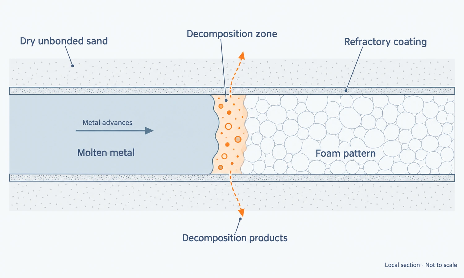
It is tempting to picture the foam instantly disappearing as the metal arrives. In practice, the advancing metal must supply heat to break down the polymer. Liquid and gaseous decomposition products form between the metal and the remaining foam, then move into and through the coating toward the surrounding sand.
This creates a moving balance: how quickly the metal advances depends partly on how quickly the foam breaks down and how effectively its byproducts can leave.
Foam density affects that balance. A denser pattern puts more polymer in the metal’s path, but simply choosing the lightest foam is not enough. The pattern still needs strength for handling, assembly, coating, and sand compaction. How well its beads fuse together also affects its surface, stability, and behavior during casting. The pattern is a controlled manufacturing input.
The coating has a similarly demanding role. It must resist metal penetration into the sand while permitting decomposition products to escape. If it restricts their escape too much, pressure can build ahead of the metal and interfere with filling. A coating that is too weak or insufficiently protective can instead allow sand penetration or surface damage.
Research on lost foam coating permeability shows that thickness affects how readily gas passes through the coating. That does not establish one ideal thickness for every casting. The appropriate combination depends on the coating formulation, foam, alloy, and part geometry.
This is why a successful lost foam process cannot be reduced to a foam density, coating thickness, or pouring temperature copied from another part. Those variables have to work together.
What lost foam casting makes easier to manufacture
The main design advantage comes from avoiding pattern withdrawal. In conventional sand casting, a reusable pattern must be removed without damaging the mold. Its shape, the mold’s separation surfaces, and any separate sand cores must accommodate that removal.
A lost foam pattern stays in place. It can therefore include shapes that would otherwise require a more complicated mold or core assembly.
Complex passages with fewer separate cores
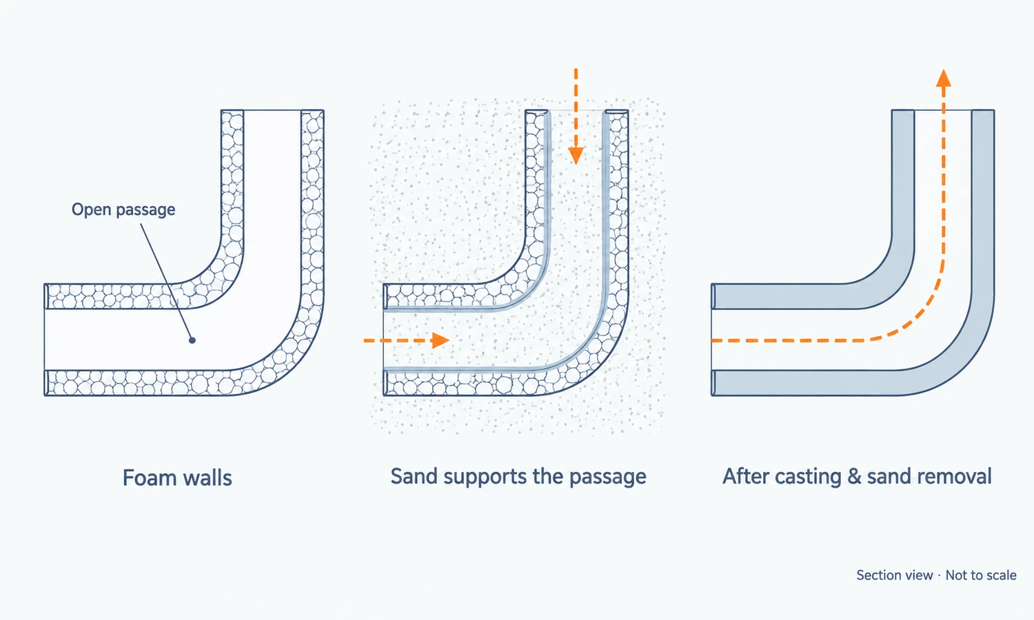
A conventional sand core is a separately made insert that creates a hollow region in the casting. In lost foam casting, loose sand can fill accessible spaces within the foam assembly and perform that function without a separate core.
Consider a housing with a curved internal passage. Foam represents the metal walls around the passage; sand fills the open space between those walls. When the metal replaces the foam and the sand is later removed, the passage remains.
The design still needs a route for sand to enter, compact adequately, and leave after casting. A completely enclosed space does not become practical merely because the outside shape can be made in foam. Narrow or difficult passages also need a realistic cleanliness and inspection plan.
Fewer mold joints and opportunities to combine parts
Eliminating the traditional mold split needed to remove a pattern can reduce mismatch and flash at that split. It can also make it possible to combine features that previously required multiple castings, cores, or assembly operations.
There can still be marks from foam tooling or glued pattern joints. Nor does casting closer to the final shape eliminate machining: sealing faces, precision bores, threads, and critical locating features may still require it.
The ASM Handbook overview of lost foam casting discusses these geometric and finishing advantages. For a particular component, their value depends on which manufacturing steps the design actually removes.
Which metals can be cast using lost foam?
Lost foam casting has established industrial uses in aluminum, gray iron, and ductile iron. Engine blocks and cylinder heads illustrate why the process is useful: their internal geometry can make conventional molding and core assembly demanding.
Steel can also be produced through specialized lost foam routes, but the process requirements differ. The alloy’s pouring conditions affect how the foam decomposes and how the mold fills. Carbonaceous residues can be particularly important in ferrous casting, including surface carbon pickup in steel.
EPS is common, while other pattern polymers, including expanded polymethyl methacrylate, may be selected for particular alloy and defect-control requirements. They are not interchangeable simply because each can form a disposable pattern. Foseco’s process guidance discusses these pattern, coating, and ferrous-casting considerations.
For a buyer, the useful question is whether the proposed foundry has demonstrated the process with the required alloy and comparable geometry. Experience producing one material does not establish capability for every other material.
What causes defects in lost foam castings?
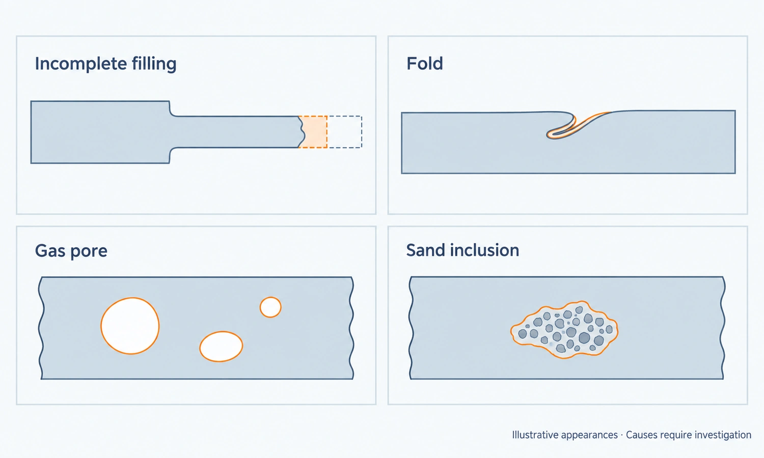
Some defects arise from the interaction between the metal and decomposing foam. Others involve familiar casting problems such as melt quality, cooling, and solidification shrinkage. A visible flaw alone rarely identifies which mechanism caused it.
| Problem | What needs investigation |
|---|---|
| Incomplete filling, or a misrun | Whether the metal lost too much heat, decomposition products restricted its advance, or the metal delivery arrangement could not fill the section. Long, thin flow paths can make filling more difficult. |
| Folds | Whether liquid polymer residues interfered with joining metal fronts, alongside local cooling and coating behavior. A fold may resemble a cold shut, but appearance alone does not establish the same cause. |
| Gas pores or blows | Foam decomposition, coating resistance, residual moisture, trapped air, and the condition of the molten metal. Several sources of gas may contribute. |
| Sand penetration or sand inclusions | Coating integrity, sand support, compaction, and the way metal entered the affected area. |
| Dimensional variation | Foam molding and stabilization, joint alignment, handling damage, distortion during coating or compaction, and contraction during cooling. |
The coupling between foam decomposition, metal flow, and defect formation is explored in Missouri S&T research on lost foam mold filling. It helps explain why raising pouring temperature or changing coating permeability is not a universal repair.
Shrinkage porosity also needs separate attention. Foam does not remove the need to feed metal into regions that contract during solidification. Gates and, where required, feeders still have to support an appropriate filling and solidification plan.
For a component under evaluation, inspection should answer its actual service requirements. Dimensions matter at mounting and machining features; pressure or leak testing may matter for a sealed housing; internal examination may be needed where hidden discontinuities are critical. A radiograph, dimensional report, and leak test answer different questions. Agreeing acceptance criteria before trials makes the results useful for a production decision.
How to compare lost foam with other casting processes
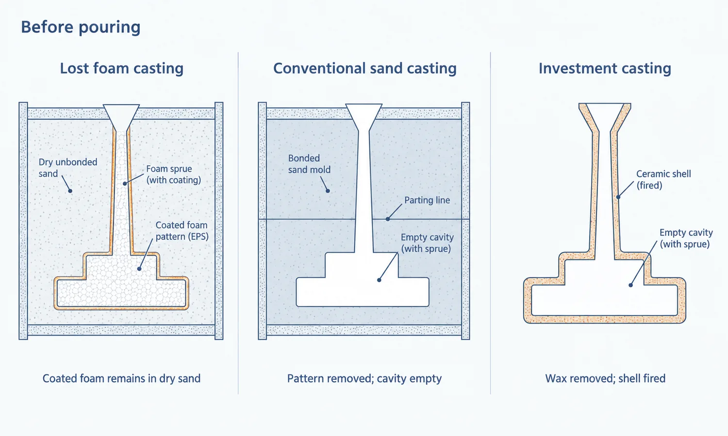
The most useful comparison starts with how each process forms the mold and what that means for the proposed part.
| Process | How the mold is prepared | What to assess for your component |
|---|---|---|
| Lost foam casting | A coated foam pattern remains in supporting dry sand and decomposes during pouring. | Whether complex passages or combined features justify pattern production and its process controls. |
| Conventional sand casting | A reusable pattern is removed before pouring; bonded molds and separate cores are commonly used. | The complexity of the mold and core assembly, potential joint mismatch, and subsequent cleaning or machining. |
| Investment casting | A wax pattern is normally removed from a ceramic shell, which is fired before metal enters the empty cavity. | Required detail, surface condition, dimensions, alloy, part size, and the economics of tooling and shell production. |
These differences explain why lost foam and lost wax casting should not be treated as the same process. They also prevent a meaningful comparison from becoming a universal ranking of accuracy or cost.
Compare the finished part, including machining
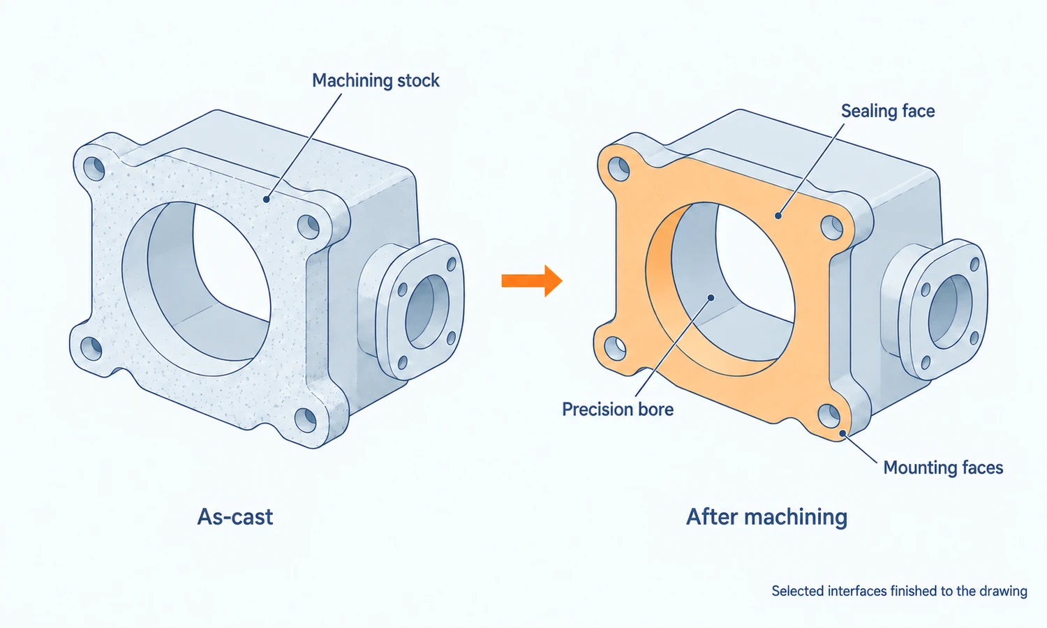
A lost foam pattern can reproduce complex geometry, but the final dimensions also depend on pattern stabilization, assembly, compaction, and metal contraction. Surface condition reflects the pattern and coating as well as casting behavior.
A generic tolerance or surface-finish figure cannot establish whether a particular drawing is achievable. Mark the features that must remain as cast and those that will be machined. Then ask for evidence of capability on comparable features, including the proposed machining references and allowances.
The DOE’s Advanced Lost Foam Casting project identifies pattern distortion, coating control, and sand compaction among the variables relevant to consistent production.
Compare total production cost
Every casting consumes a foam pattern, and repeated production commonly needs dedicated pattern tooling. Molding, assembly, coating, drying, and handling therefore remain part of the production cost.
Those costs may be offset by fewer separate cores, less assembly, reduced cleaning, or less machining. The benefit is strongest when those savings are significant for the actual design. For a simple part that already casts efficiently by another route, there may be fewer operations to eliminate.
Compare the cost of an accepted finished component at the expected order quantities. Include tooling and development, each foam pattern, losses from rejected castings, and any remaining cleaning, machining, inspection, or assembly. There is no single annual volume at which lost foam becomes the cheapest choice. Complexity, repeatability, tooling investment, and the work eliminated across the production route determine whether it pays.
Evaluating a lost foam route with YTD Foundry
Lost foam casting deserves consideration when a part’s passages, core assembly, or multiple manufacturing operations make the existing route difficult or costly. The next step is to review a real drawing against the alloy, critical features, order quantities, and inspection requirements.
YTD Foundry provides lost foam casting, investment casting, sand casting, and die casting for custom components made from drawings or physical samples. Tooling, machining, inspection, surface finishing, and finished-part delivery are organized around each project’s requirements.
For a process review, provide a drawing or model, the required alloy, expected quantities, and the features that determine whether the part will work: critical dimensions, internal passages, machining requirements, and applicable acceptance tests. These details help establish a suitable casting and finishing route.
That review should establish whether lost foam simplifies the complete component while meeting its dimensional, functional, and quality requirements consistently.
FAQs
Does Lost Foam Casting Require Vacuum?
No. Some industrial lines use negative pressure to stabilize the sand bed or manage gas during filling, while other established arrangements do not. Where vacuum is used, its level and timing must match flask sealing, sand, coating, pattern, and pouring conditions.
Which Metals Can Be Used for Lost Foam Casting?
Industrial applications include aluminum, gray iron, and ductile iron, with specialized steel and other alloy routes also available. Each alloy changes temperature, fluidity, oxidation, polymer decomposition, carbon-related risks, coating, and feeding, so capability must be confirmed for the specific material and part.
Does Lost Foam Casting Need Draft or Sand Cores?
The casting does not need conventional draft solely to withdraw the foam from sand, and sand-filled passages can replace many separate cores. The foam tooling may still need draft and split lines, while inaccessible or unsupported passages may still require a core, insert, machining, or redesign.
How Are Lost Foam Castings Inspected?
Inspection may combine visual and dimensional checks, CMM, metallography, sectioning, radiography or CT, penetrant testing, leak or pressure testing, flow testing, and mechanical testing. The drawing should define the method, critical zones, coverage, sampling, and acceptance criteria.
What Determines Lost Foam Casting Cost?
Cost includes reusable foam tooling, every consumed pattern, assembly, coating, drying, sand handling, pouring, metal yield, cleaning, inspection, machining, scrap, and rework. An order for 1,000 single-piece castings needs at least 1,000 acceptable part patterns before trials or scrap, even though the tooling is reusable.
Is Lost Foam Casting an Environmentally Friendly Process?
Unbonded sand can be reclaimed, but that does not make the process zero-waste or zero-emission. The U.S. EPA identifies polymer vapors, VOCs, hazardous air pollutants, and particulates as relevant emissions. Silica-bearing sand also requires dust controls under the applicable OSHA silica framework.
Is lost foam casting the same as full-mold casting?
The names sometimes overlap in industry usage. A common distinction is that lost foam casting uses dry, unbonded sand, while full-mold casting uses bonded or green sand around an expendable pattern. Evaporative-pattern casting is the broader category. When comparing suppliers or technical descriptions, establish the actual mold arrangement rather than relying on the process name.
Can ordinary packaging foam or a 3D-printed pattern be substituted?
They should not be assumed equivalent to a qualified casting pattern. Polymer chemistry, density, surface condition, joints, and decomposition behavior affect the result. Cut foam and suitable printed expendable patterns can support development, but a successful prototype does not by itself prove that a different pattern material or production method will cast consistently.