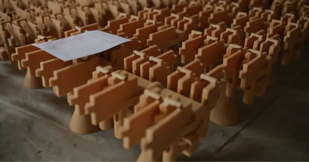
A wax tree is an assembly of investment casting patterns connected to a central wax sprue before ceramic shell building.
It does more than hold multiple patterns together. After the wax is removed, the same geometry becomes the network through which molten metal reaches each casting cavity. For this reason, the number of parts on a tree, their spacing and orientation, and the size and location of the gates can influence shell building, metal flow, casting defects, production efficiency, and casting yield.
What Is a Wax Tree in Investment Casting?
Each wax pattern in investment casting represents one future metal casting. For small and medium components, producing a separate ceramic shell and pouring each pattern individually would usually be inefficient.
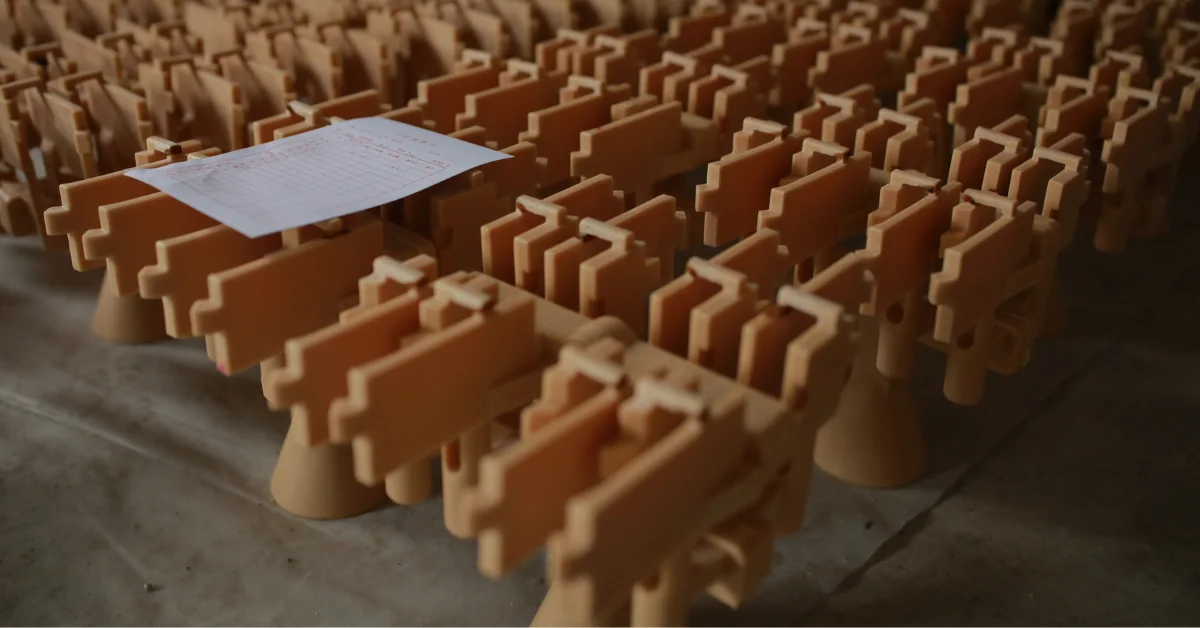
Instead, several wax patterns are commonly attached to a central wax sprue to form a wax tree, also called a wax assembly or cluster.
The Investment Casting Institute’s explanation of wax tree assembly describes two main functions of the central sprue. It provides a structure on which multiple patterns can be assembled, and after dewaxing it creates a flow path through which molten alloy reaches those pattern cavities.
This makes the wax tree much more than a convenient holder.
It is a sacrificial model of both the products and a large part of the future metal-delivery system.
Wax Pattern, Sprue, Gate, and Runner: What Is on a Wax Tree?
The terminology used around investment casting trees can vary slightly between foundries, but the basic structure is straightforward.
| Feature | Function |
|---|---|
| Wax Pattern | Represents the geometry of the future metal casting |
| Central Sprue | Supports the patterns and later forms the main metal-flow passage |
| Gate | Connects the individual pattern to the sprue or runner |
| Runner / Branch | Distributes metal between the main sprue and individual gates when the layout requires it |
| Pouring Cup | Forms the entry region through which metal enters the finished ceramic mold |
| Wax Tree / Cluster | The complete assembly of patterns and gating features |
In a simple investment casting tree, patterns may connect almost directly to a central sprue through individual gates. More complex layouts can contain additional branches or runner features.
These wax features disappear later, but their geometry does not.
Once the ceramic shell has been built and the wax removed, they become cavities through which molten metal must flow.
For a broader explanation of how sprues, runners, gates, and feeding systems work after pouring begins, see YTD’s Gating System in Casting guide.
Why Small Investment Castings Are Grouped on a Wax Tree
Tree assembly has an obvious production advantage: several parts can move through shell building and casting together.
If twenty small patterns can share one ceramic shell, the foundry does not have to prepare twenty separate molds and perform twenty separate pours.
The same wax assembly can move through shell coating, drying, dewaxing, shell firing, pouring, shell removal, and cut-off as one production unit.
This is why tree assembly is especially common for relatively small investment castings.
However, the goal is not to fit the maximum possible number of patterns onto every sprue.
Adding more parts can improve productivity, but only while the resulting tree remains practical to shell, handle, pour, solidify, and cut apart.
The most efficient wax tree is therefore not necessarily the tree with the highest pattern count.
It is the tree that produces the greatest number of acceptable castings efficiently.
How Wax Patterns Are Attached to the Tree
Tree assembly normally begins after individual wax patterns have been produced and inspected.
A pattern with serious distortion, incomplete filling, surface damage, or another unacceptable wax defect should be corrected or rejected before shell building. Once a defective pattern has been coated with several ceramic layers and cast in metal, far more process cost has already been added.
Accepted patterns are positioned according to the planned tree layout and joined to the wax gating system.
The connection between the pattern and sprue must be strong enough to survive handling and shell building, but the shape of this joint is also important for the later casting process.
When dewaxing removes the pattern, the gate joint becomes part of the ceramic flow path.
A badly formed wax connection can therefore become a badly formed metal-flow passage.
This is one reason wax tree assembly is not simply manual pattern attachment. It is the physical creation of the gating geometry that will later control molten metal.
Pattern Spacing Affects Ceramic Shell Building
Before a tree can be poured, it must first become a ceramic mold.
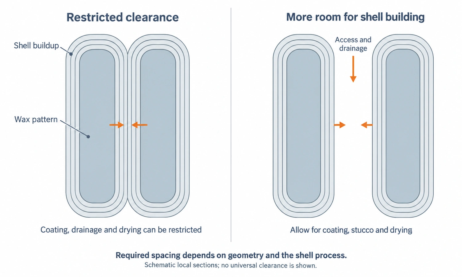
The complete wax assembly is repeatedly coated with ceramic slurry and refractory stucco. Each layer must coat the wax surfaces properly, drain, and dry before subsequent layers are added.
The Investment Casting Institute describes this process in its shell building overview: the wax tree is repeatedly dipped and stuccoed until a laminated ceramic shell capable of surviving the casting process has been built.
This creates a practical limitation on wax tree density.
If patterns are positioned too close together, the narrow space between them can become more difficult to coat, drain, stucco, and dry consistently.
Tree layout must therefore leave enough space for the shell-building process.
This is an important distinction because a layout that looks efficient from the perspective of fitting parts onto a sprue may be inefficient once ceramic shell production is considered.
For more detail on how the slurry, stucco, drainage, and drying stages work together, see YTD’s Ceramic Slurry in Investment Casting guide.
Pattern Orientation Affects How Molten Metal Fills the Casting
The wax tree eventually disappears, but its geometry remains inside the ceramic shell.
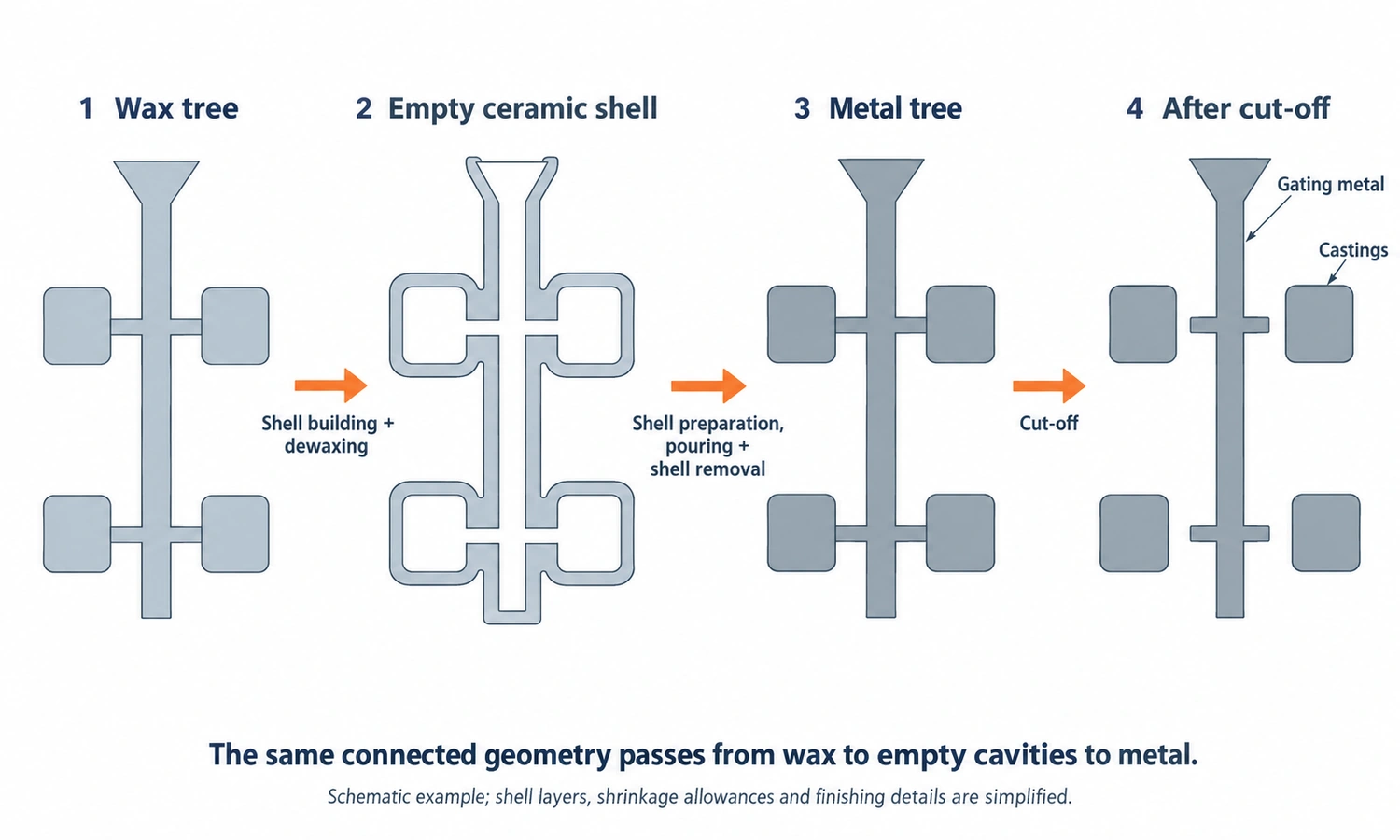
During dewaxing, the wax sprue, gates, and patterns leave behind a connected system of empty cavities.
During pouring, molten metal follows those same passages.
The former central wax sprue becomes a major metal-flow channel. The gates become the entrances into each component cavity, while the pattern spaces become the actual castings.
Pattern orientation therefore matters.
A casting may contain thin sections that need to fill before they lose too much temperature, heavy sections that remain hot for longer, or changes in wall thickness that make filling and solidification more difficult.
The location of the gate and the orientation of the component relative to the sprue influence how metal reaches these areas.
Tree design is therefore closely connected with gating design.
The foundry is not simply deciding:
Where can this pattern physically fit?
It is also deciding:
How should molten metal enter and fill this component after the wax is gone?
Why More Parts per Wax Tree Is Not Always Better
Putting more patterns on each tree can reduce shell-building and pouring cost per part, so increasing tree density is attractive.
But there is always a point where additional patterns can make the process less efficient rather than more efficient.
A larger tree requires more wax, more shell material, greater handling capacity, and a larger metal pour. Patterns may also have to be positioned closer together or farther from the ideal gating location.
Thermal interaction matters as well.
Several hot castings positioned close together do not cool independently. Nearby components and runner sections can exchange radiant heat, changing local solidification behavior.
This is particularly relevant in investment casting because the complete cluster is poured as one connected metal assembly.
YTD’s casting simulation guide explains how tree orientation, runner position, filling sequence, temperature distribution, and solidification can be evaluated before production for suitable projects.
The engineering target is therefore not:
maximum patterns per tree
but:
efficient patterns per tree without compromising repeatable casting quality
Small Castings and Large Castings Use Different Wax Tree Layouts
Not every investment casting tree looks like a central sprue covered with dozens of small parts.
That arrangement is particularly suitable for small components because many lightweight patterns can share the same sprue and shell.
As casting size increases, the number of parts that can practically share a tree normally decreases.
A very large investment casting may be poured as a single component with its own gating system.
At that point, the word tree may sound slightly misleading because there may be only one product cavity attached to the sprue.
This size difference also changes the relationship between product weight and gating weight.
For a tree containing many very small components, the central sprue and gates can weigh more in metal than all the usable parts combined.
For a large casting poured individually, the casting itself may represent the majority of the total pour weight.
Neither situation is automatically better or worse.
The required ratio depends on the component and the metal-flow system needed to produce it.
Wax Tree Weight and Metal Pour Weight Are Not the Same Thing
The wax tree itself may be physically light.
The metal assembly that replaces it after pouring is much heavier because the density of casting alloys is far greater than that of pattern wax.
What matters for furnace and pouring calculations is therefore not simply how much the wax tree weighs.
The foundry needs to determine the volume represented by the patterns, sprue, gates, and runners and then consider the density of the alloy that will replace that volume.
A tree for stainless steel will have a different metal weight from geometrically identical cavities filled with aluminum.
This becomes particularly important when evaluating the maximum practical casting or tree size.
If a furnace has a given melt or pour capacity, that capacity must cover the complete metal tree.
It cannot all become finished product because the metal sprue, gates, runners, and any necessary feeding sections must also be filled.
YTD discusses this distinction in more detail in Casting Yield Explained: Part Weight, Pour Weight, Gating Weight & Metal Returns.
How Wax Tree Design Affects Casting Yield
Casting yield measures how much of the metal poured becomes acceptable casting rather than gating, feeding, or other process metal.
A simplified expression is:
Casting Yield = Good Casting Weight ÷ Total Pour Weight × 100%
Wax tree design directly affects this relationship because the sprue and gates represented by the wax assembly later become metal that must be cut away.
Suppose a tree contains many small parts. The combined product weight may be relatively low compared with the heavy central sprue required to distribute metal to all of them.
The resulting casting yield can therefore be quite low even when the process is operating correctly.
A larger individual casting may have a much higher part-to-gating ratio.
But higher yield should never be pursued independently from casting quality.
If runners or gates are reduced too aggressively simply to save metal, the process can suffer from poor filling, premature freezing, shrinkage, or other defects.
A higher theoretical yield has little value if the scrap rate rises.
Casting yield should be the result of a sound gating system, not a target that overrides filling and solidification requirements.
Simple and Complex Parts Can Require Very Different Tree Designs
Two components with the same weight do not necessarily need similar wax trees.
A compact part with relatively uniform wall thickness may be attached through a simple gate and fill predictably.
Another part of the same weight may contain long thin sections, abrupt wall-thickness transitions, isolated heavy areas, or several difficult flow paths.
That geometry can require a different gate position, additional gating, or a completely different tree orientation.
This is why a foundry cannot reliably determine tree design only from part weight and annual quantity.
The actual geometry must be considered.
This is also why YTD reviews gating and manufacturability during the early stages of investment casting design rather than waiting until wax patterns have already been produced.
The Wax Tree Becomes the Cavity Inside the Ceramic Shell
After assembly, the wax tree moves into ceramic shell building.
Slurry and refractory particles gradually form a ceramic layer around every pattern, gate, and sprue surface.
Once the shell has reached the required thickness and strength, the wax is removed.
The Investment Casting Institute describes the ceramic shell as the mold that ultimately receives the molten metal. Its process overview also makes an important distinction: the wax assembly is temporary, while the ceramic shell is a one-time casting mold.
The transformation can be understood as:
wax patterns and gating → ceramic shell around the tree → wax removal → connected ceramic cavities
Molten metal then fills those cavities.
This is why the wax tree itself should not be confused with the casting mold.
It is the sacrificial pattern assembly from which the internal geometry of the ceramic mold is created.
For the distinction between wax tooling, patterns, ceramic cores, and ceramic shell molds, see YTD’s Investment Casting Mold guide.
The Wax Tree Becomes a Metal Tree After Pouring
After the ceramic mold is filled and the alloy solidifies, the tree exists again—but now in metal.
The individual castings remain connected to solid metal gates and the central sprue.
The ceramic shell is broken away to expose this metal cluster.
Individual castings can then be cut from the tree, and the remaining gate areas are ground or finished according to the part requirements.
Gate position therefore affects more than filling.
A gate should ideally be located where it can support good metal flow without creating unnecessary difficulty during cut-off and finishing.
Placing a large gate on a critical sealing surface, cosmetic surface, or difficult-to-access feature can create additional downstream work even if the casting fills successfully.
Good tree design considers both directions of the process:
how molten metal gets into the part
and
how the finished casting gets off the tree
What Happens to the Metal Sprue and Gates After Cut-Off?
The metal left in the central sprue, gates, runners, and rejected castings is not necessarily discarded.
In foundry terminology, suitable material of known composition can become foundry returns. The American Foundry Society defines foundry returns as gates, sprues, runners, risers, and scrapped castings returned to the furnace for remelting.
Whether a particular return is remelted internally depends on alloy identity, cleanliness, contamination control, specification requirements, and the foundry’s melt-management procedure.
Other material may be separated and sent to a qualified recycler or alloy-processing company instead.
This is particularly important with high-value alloys where chemistry and contamination require careful segregation.
The fact that sprue metal can be recovered does not make it free.
That material has already been melted, poured, shelled, handled, cut, and sorted. Remelting consumes additional energy, and normal melting and handling also create material losses.
This is another reason foundries try to reduce unnecessary gating metal without sacrificing process reliability.
Can Different Parts Be Put on the Same Wax Tree?
They can, but it is not always desirable.
Different components can have different wall thicknesses, volumes, gate requirements, and solidification behavior.
A tree layout that works well for one geometry may not distribute metal equally well to another.
Mixed trees can also complicate production planning, quantity control, cut-off, traceability, and inspection.
For stable serial production, identical or closely compatible components often make process control simpler.
However, there is no rule requiring every pattern on a tree to be identical.
The real question is whether the complete assembly can be shelled, filled, solidified, separated, and controlled consistently.
Can 3D-Printed Patterns Be Used on a Casting Tree?
Yes.
Conventional production patterns are usually made by injecting wax into reusable tooling, but prototype and low-volume patterns can also be produced using additive manufacturing.
Those sacrificial patterns can then be incorporated into an investment casting assembly if their material and burnout behavior are compatible with the qualified shell process.
The Investment Casting Institute recognizes both injected wax patterns and additively manufactured sacrificial patterns within modern investment casting practice.
This can be useful when a customer needs prototype castings before committing to production tooling.
For repeat production, conventional wax injection normally remains more economical because the reusable tool can produce large numbers of consistent patterns.
YTD discusses the tooling and printed-pattern options in more detail in its Investment Casting Mold guide.
How a Wax Tree Is Designed for a New Investment Casting
There is no universal wax tree design that can be copied from one casting to another.
Development starts with the actual component.
The engineer has to consider part geometry, alloy, wall thickness, casting weight, production quantity, critical surfaces, filling distance, solidification behavior, shell-building access, and later cut-off requirements.
For small components, the challenge may be finding the most efficient number and orientation of patterns around a shared sprue.
For a larger casting, the more important question may be how the individual component should be gated and fed while keeping total pour weight within process capacity.
For suitable difficult castings, simulation can be used to evaluate alternative layouts before the process is finalized.
However, simulation does not eliminate physical validation. Actual wax assembly, shell building, pouring, and first-article casting still show whether the proposed process works under production conditions.
How YTD Designs Wax Trees for Investment Casting
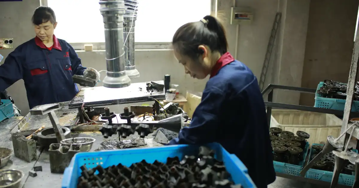
At YTD Foundry, wax tree design is treated as part of the complete investment casting process, not simply as a pattern-assembly step.
After wax patterns are produced and inspected, the proposed tree is evaluated according to the component geometry, material, wall thickness, number of parts, gate requirements, total pour weight, shell-building access, and eventual cut-off.
For suitable projects, casting simulation can also be used during process development to evaluate filling sequence, temperature distribution, solidification, hot spots, and gating or feeding changes before the process is finalized.
Once the tree layout has been validated, the assembly moves through silica-sol shell building, dewaxing, shell preparation, metal pouring, shell removal, cut-off, heat treatment, machining where required, and inspection.
The objective is not to place the maximum possible number of wax patterns on one sprue.
It is to create a tree that repeatedly produces acceptable castings with an efficient use of shell capacity, metal, labor, and downstream processing.
Final Thoughts
A wax tree is more than a way to hold investment casting patterns together. Its layout determines how several parts share one ceramic shell and, after dewaxing, becomes the pathway through which molten alloy reaches each casting.
Good tree design therefore balances pattern count with shell-building access, filling, solidification, casting yield, cut-off, and repeatability. The best tree is not necessarily the largest or most densely packed—it is the one that consistently produces acceptable castings efficiently.
FAQs
What Is a Wax Tree in Casting?
A wax tree is an assembly of one or more sacrificial casting patterns connected to a central wax sprue and gating system. It is mainly used in investment or lost-wax casting before ceramic shell building.
Why Are Wax Patterns Put on a Tree?
Several patterns can share one ceramic shell and one pouring operation, improving production efficiency. The same sprue and gate geometry also creates the passages through which molten metal later reaches the casting cavities.
Is a Wax Tree the Same as a Gating System?
Not exactly. The wax tree includes both the product patterns and the wax gating features. After dewaxing, the sprue, runner, and gate portions create the metal-delivery passages, while the pattern portions create the product cavities.
How Many Parts Can Be Put on One Wax Tree?
There is no fixed number. Small components may be assembled in relatively large quantities, while a large investment casting may be poured individually. Part size, geometry, shell access, pour weight, filling, and solidification all affect the decision.
Does Putting More Parts on a Tree Always Reduce Cost?
No. More parts can improve productivity, but overcrowding can make shell building, metal filling, handling, solidification, or cut-off more difficult. The relevant measure is acceptable castings produced efficiently, not simply pattern count.
What Happens to the Wax Tree During Dewaxing?
The wax is removed from the ceramic shell, leaving connected cavities where the wax patterns, sprue, and gates previously existed. Molten alloy later fills those cavities.
What Happens to the Metal Tree After Casting?
The ceramic shell is removed and each casting is cut from the metal sprue and gates. Suitable identified metal returns can then be remelted under controlled conditions or sent for appropriate recycling.