The term investment casting mold can mean different things.
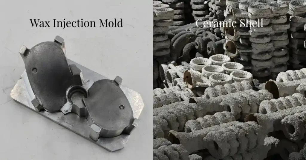
Investment casting may use reusable tooling to make wax patterns and, when required, ceramic cores. But the mold that actually receives molten metal is normally an expendable ceramic shell built around those patterns.
The basic relationship is:
reusable tooling → wax pattern and optional ceramic core → ceramic shell mold → metal casting
Understanding this distinction makes tooling cost, mold life, internal cavities, prototyping, and casting accuracy much easier to evaluate.
Wax Tooling, Core Tooling, and Ceramic Shells Have Different Functions
The first distinction is between reusable production tooling and the one-time casting mold.
| Item | Main Function | Reusable? |
|---|---|---|
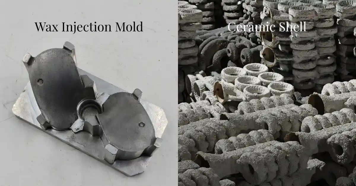
| Wax Injection Tooling | Produces wax patterns | Yes |
| Ceramic Core Tooling | Produces ceramic cores for selected internal passages | Usually yes |
| Ceramic Shell Mold | Contains molten metal during casting | No |
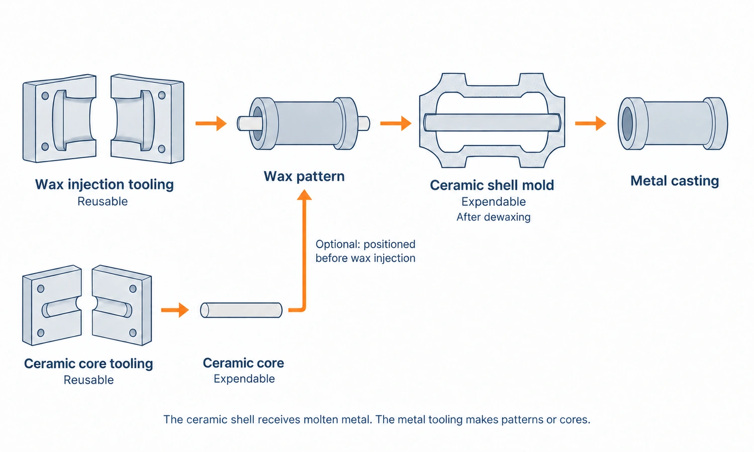
Wax tooling and core tooling belong to the pattern-making stage.
The ceramic shell belongs to the metal-casting stage.
This distinction matters commercially as well. When a foundry quotes a mold fee or tooling charge, it normally refers to reusable tooling—most commonly the wax injection tool—not to the ceramic shell consumed during every casting cycle.
Wax Injection Tooling Creates the Wax Pattern
For repeat production, investment casting normally begins with a reusable wax injection tool.
Wax is injected into the cavity, allowed to cool, and removed as a pattern representing the future casting.
The basic dimensional chain is:
tool cavity → wax pattern → ceramic shell cavity → metal casting
However, the tool cannot simply be an exact copy of the finished CAD model.
The tooling engineer has to account for wax shrinkage, metal shrinkage, heat-treatment movement, and any machining allowance required on the finished component.
The tool also has to produce wax patterns consistently.
Wax must fill the cavity properly, cool without excessive distortion, and leave the tool without being damaged. Undercuts or multiple pull directions may require removable inserts, slides, loose pieces, or other tooling features.
Parting-line location also matters because it affects wax flash, pattern finishing, and ease of mold opening.
The real test of a wax tool is therefore not simply whether the metal cavity measures correctly.
It is whether the tool can repeatedly produce stable wax patterns that lead to acceptable castings.
YTD handles tooling development as part of the investment-casting process, including DFM review, tool manufacture, trial wax injection, and pattern inspection. YTD casting mold manufacturing
Ceramic Core Tooling Creates Internal Casting Geometry
Some investment castings contain internal passages that cannot be created by the external wax pattern alone.
These features may require a ceramic core.
A ceramic core is a sacrificial refractory shape placed inside the wax pattern. During pouring, molten metal solidifies around the core. After casting, the core is removed and leaves the required internal cavity.
Ceramic cores are particularly useful for geometry such as curved, branched, narrow, or inaccessible internal passages.
Turbine blades with internal cooling channels are a familiar example.
For repeat production, ceramic cores are commonly produced using dedicated core tooling or a ceramic core die.
That means one casting project can potentially require two different sets of reusable tooling:
wax tooling for the external pattern
and
core tooling for the internal ceramic core
They perform completely different jobs.
How Ceramic Cores Are Manufactured
Traditional ceramic cores are often made by ceramic injection molding.
A ceramic feedstock containing refractory material and a temporary binder is injected into a reusable core die. The molded green core is then removed, the temporary binder is eliminated, and the core is fired or sintered to develop the strength and thermal stability required for casting.
The basic sequence is:
ceramic feedstock → core tooling → green core → binder removal → firing → finished ceramic core
Core tooling can be challenging because the ceramic core itself is often geometrically complex.
Thin ribs, curved channels, branches, and delicate sections all have to be formed and removed from the tool without damaging the unfired core.
The tooling design must also allow for dimensional changes during molding and firing.
A distorted ceramic core directly changes the internal geometry of the finished metal part, so core dimensions and stability can be just as important as wax-pattern accuracy.
How Ceramic Cores and Wax Tooling Work Together
Once the ceramic core has been manufactured and inspected, it is positioned inside the wax injection tool.
Wax is then injected around the ceramic core.
The result is a composite pattern:
wax exterior + ceramic core inside
The core therefore becomes physically embedded in the wax pattern.
This also means the position of the core is critical.
If it shifts inside the wax tool, the external wax pattern may still look correct while the future casting develops incorrect wall thickness or misplaced internal passages.
After wax injection, the cored pattern continues through the normal investment-casting process.
The wax pattern is assembled and covered with ceramic shell material. During dewaxing, the wax disappears, but the ceramic core remains.
Molten metal later fills the space between the outer ceramic shell and the internal ceramic core.
After solidification, the shell is removed from the outside and the ceramic core is removed from inside the casting using a process suitable for the core material and component geometry.
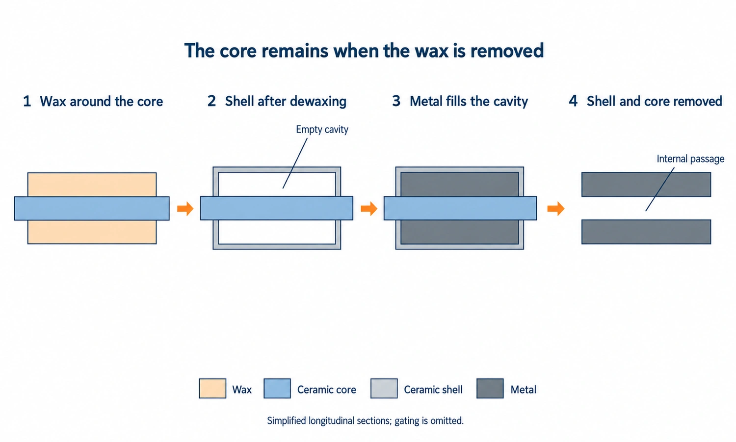
The Ceramic Shell Is the Actual Casting Mold
The ceramic shell is different from wax tooling and core tooling because it is not reusable production equipment.
It is the actual expendable mold into which molten metal is poured.
Wax patterns are assembled onto a wax sprue or tree and repeatedly coated with ceramic slurry and refractory stucco.
Each layer is dried before the next is added until the shell has enough thickness and strength for dewaxing, handling, firing, and pouring.
Once the wax is removed, the shell contains the negative geometry created by the wax pattern.
Molten alloy is poured into this cavity and allowed to solidify.
The shell is then broken away.
This creates an important difference in investment-casting economics:
one wax tool can make many patterns, but every casting cycle requires a new ceramic shell.
For cored parts, the shell defines the external geometry while the ceramic core defines selected internal geometry.
How Wax Tooling and Ceramic Cores Affect Casting Accuracy
Final investment-casting accuracy is not determined by one mold alone.
For a normal uncored component, the dimensional chain may include:
tooling → wax shrinkage and distortion → shell building → metal shrinkage → heat treatment → machining
For a ceramic-core casting, another chain is added:
core tooling → ceramic-core shrinkage or warpage → core positioning → metal casting
This is why a highly accurate tool does not automatically guarantee a perfectly accurate finished casting.
Foundries use process allowances and experience to compensate for predictable dimensional changes, but new tooling still needs trial patterns and first castings before the production process is considered stable.
Critical features that require tighter control can then be CNC machined after casting.
Aluminum vs. Steel Wax Tooling
Wax injection tooling is commonly made from aluminum or steel.
Aluminum is relatively easy to machine and modify. It can reduce tooling cost and lead time, making it useful for many small and medium production programs.
Steel provides greater rigidity and wear resistance and may be preferable for large tooling, difficult geometry, or long-running production.
Neither material is universally better.
The right choice depends on factors such as:
- mold size;
- geometry;
- expected production volume;
- required tool life;
- dimensional stability;
- lead time;
- budget.
YTD manufactures both aluminum and steel wax tooling according to project requirements. YTD casting mold manufacturing
The useful question is therefore not whether steel is always better than aluminum, but whether the selected tooling construction is appropriate for the expected production program.
How Investment Casting Wax Tooling Is Manufactured
For many parts, wax tooling is CNC machined directly from aluminum or steel.
The cavity, parting surfaces, inserts, locating features, slides, and other tool components are manufactured according to the approved design and then assembled.
Surface condition matters because the wax pattern reproduces the tool surface, and that surface is later transferred through the ceramic shell to the metal casting.
After the tool is assembled, trial wax patterns are produced.
These patterns are checked for filling, dimensions, flash, distortion, surface condition, and removal from the tool.
If a problem appears, modifying the tool at this stage is usually far less expensive than discovering the same issue after shell building and metal casting have begun.
For suitable larger tooling projects, YTD can also use a cast tooling blank followed by CNC finishing instead of machining the entire tool directly from solid billet.
Tooling Design Should Be Connected to Casting DFM and Simulation
Wax-tool design and metal-casting design are related but not identical.
The wax tool needs to answer questions such as:
Can the wax fill the cavity?
Will it cool predictably?
Can the pattern be removed safely?
The later casting process asks different questions:
Can molten metal fill the shell completely?
Where will solidification begin?
Are heavy sections properly fed?
Where could shrinkage or hot spots develop?
For suitable projects, casting simulation can be used during tooling and process development to evaluate filling, temperature distribution, solidification, shrinkage risk, gating, and feeding before production decisions are finalized.
The value is not the simulation image itself.
It is the opportunity to change the tooling or casting process before those changes become expensive.
Does Every Investment Casting Project Need Hard Tooling?
No.
Reusable wax tooling makes the most economic sense when the same pattern will be produced repeatedly.
For prototypes and very low quantities, tooling may represent a large portion of total project cost.
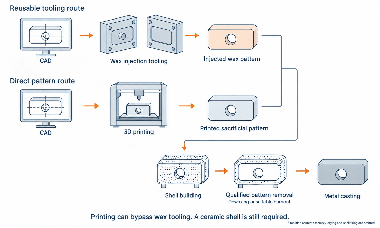
In these cases, a sacrificial pattern can sometimes be produced directly by additive manufacturing.
The route becomes:
CAD → printed sacrificial pattern → ceramic shell → metal casting
This eliminates the initial wax-tooling step.
Printed patterns are useful for prototype and low-volume work, especially while a design is still changing.
However, they do not automatically replace hard tooling for production.
Their per-pattern cost is normally higher, and pattern material, dimensional behavior, surface condition, and burnout all need to be suitable for the investment-casting process.
Once production volume increases and the design stabilizes, reusable wax tooling generally provides better economics and repeatability.
Can Ceramic Cores Be Made Without Core Tooling?
Yes.
Additive manufacturing can also produce ceramic cores directly from digital geometry.
This is especially useful when the internal passage is so complex that traditional core tooling becomes difficult to manufacture or demold.
Printed cores can reduce or eliminate the need for dedicated core dies in prototype, low-volume, or highly complex applications.
However, the same economic principle applies.
Avoiding tooling reduces upfront cost, but the individual printed core may cost more than an injection-molded core.
For stable repeat production, conventional ceramic-core tooling can still provide advantages in cycle time and unit cost.
The choice therefore depends on internal geometry, quantity, tolerance, core material, and qualification requirements.
Investment Casting Tooling Cost and Tool Life
There is no standard price for an investment casting mold.
A simple two-piece aluminum wax tool and a large steel tool with multiple slides and inserts are fundamentally different manufacturing projects.
Part size affects tooling material and machining time, but geometry often affects cost even more.
Undercuts, deep cavities, multiple pull directions, removable inserts, tight tolerances, and core-positioning features can all make the tool more complicated.
If a ceramic core is required, dedicated core tooling may become an additional cost.
This is important when comparing supplier quotations.
One quotation may cover only the wax tool, while another includes wax tooling, core tooling, checking fixtures, or other dedicated production equipment.
Tool life also varies.
Steel generally provides greater wear resistance than aluminum, but actual service life depends on geometry, moving components, injection conditions, maintenance, and required dimensional consistency.
The correct tooling decision should therefore consider lifetime production, not only the quantity on the first order.
Who Owns the Investment Casting Tooling?
Tool ownership should be clarified before the tooling order is placed.
A customer may pay a tooling charge while the foundry stores and maintains the mold for future production.
That does not automatically define ownership.
The commercial agreement should make clear whether the customer owns the tool, how long it will be stored, who pays for major maintenance or modification, and what happens if the project moves to another supplier.
If ceramic core tooling, checking fixtures, or other dedicated tooling are included, those items should also be identified separately.
This prevents the phrase “mold fee” from covering several different assets without explanation.
What Information Does a Foundry Need Before Designing the Tooling?
A 3D model is useful, but tooling design requires more than visible geometry.
The foundry also needs to understand the alloy, expected production volume, dimensional requirements, machining, and critical functional features.
A 2D drawing remains valuable because it identifies tolerances, datums, machined surfaces, and other requirements that may not be fully defined by the CAD model.
Internal cavities deserve particular attention.
The foundry needs to decide whether they can be created through normal pattern geometry or whether a ceramic core or another core strategy is required.
Expected lifetime quantity also influences whether aluminum tooling, steel tooling, printed patterns, or printed cores make the most sense.
If a usable drawing or CAD model does not exist, reverse engineering from an existing component can provide the starting geometry.
The objective is not simply to duplicate the part.
It is to design a repeatable manufacturing route for the part.
How YTD Handles Investment Casting Tooling Development
At YTD Foundry, reusable wax injection tooling is designed and manufactured as part of the in-house investment-casting workflow.
Tooling development begins with the customer’s drawing, 3D model, or sample.
The engineering review considers shrinkage, wall thickness, tolerance, parting structure, wax-pattern removal, machining requirements, and any core requirements before tooling is finalized.
Suitable projects can also use casting simulation during process development.
After approval, aluminum or steel tooling is manufactured according to the project needs. Trial wax patterns are then produced and inspected before the tool is released for repeat production.
When a casting requires a ceramic core, that requirement is treated separately from normal wax tooling because the core has its own geometry, material behavior, positioning, and potentially its own production tooling.
The ceramic shell is different again.
It is not reusable tooling but the expendable refractory mold built around the wax assembly for each pour.
Keeping these functions separate makes the process much easier to understand:
wax tooling creates the pattern
core tooling creates the internal sacrificial core when required
the ceramic shell becomes the actual casting mold
Final Thoughts
Investment casting uses both reusable tooling and an expendable casting mold.
Wax tooling creates the external pattern, while ceramic core tooling may be required for complex internal passages. These elements are then enclosed by a ceramic shell, which becomes the actual one-time mold for molten metal.
The key tooling question is therefore not simply what “mold” a part needs, but which geometry must be created by wax tooling, which features require cores, and how those elements work together through the complete casting process.
FAQs
What Is the Mold in Investment Casting?
The term can refer to different things. A reusable wax injection tool produces wax patterns, while the ceramic shell built around those patterns is the expendable mold that actually receives molten metal.
Is Investment Casting Tooling Reusable?
Wax tooling is reusable and can produce many patterns. Ceramic core tooling, when required, is also generally reusable. The ceramic shell mold is normally used only once.
Do Ceramic Cores Need Their Own Molds?
Traditional injection-molded ceramic cores normally require dedicated core tooling. Printed ceramic cores can sometimes eliminate that tooling for prototypes, low volumes, or very complex geometries.
How Is a Ceramic Core Used With a Wax Pattern?
The finished ceramic core is positioned inside the wax injection tool, and wax is injected around it. During dewaxing, the wax is removed while the ceramic core remains to create the internal cavity during metal pouring.
Is Aluminum or Steel Better for Wax Tooling?
Neither is always better. Aluminum can reduce cost and lead time, while steel generally provides greater rigidity and wear resistance. The correct choice depends on size, complexity, volume, and expected tool life.
Can Investment Casting Be Done Without Wax Tooling?
Yes. Printed sacrificial patterns can be used for prototypes and low-volume production, eliminating conventional wax injection tooling. For repeat production, reusable hard tooling is usually more economical.
Does Accurate Tooling Guarantee an Accurate Casting?
No. Tool accuracy is only one part of the dimensional chain. Wax shrinkage, ceramic-core variation, shell building, alloy shrinkage, heat treatment, and machining can all influence final dimensions.