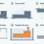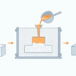
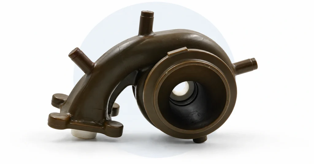
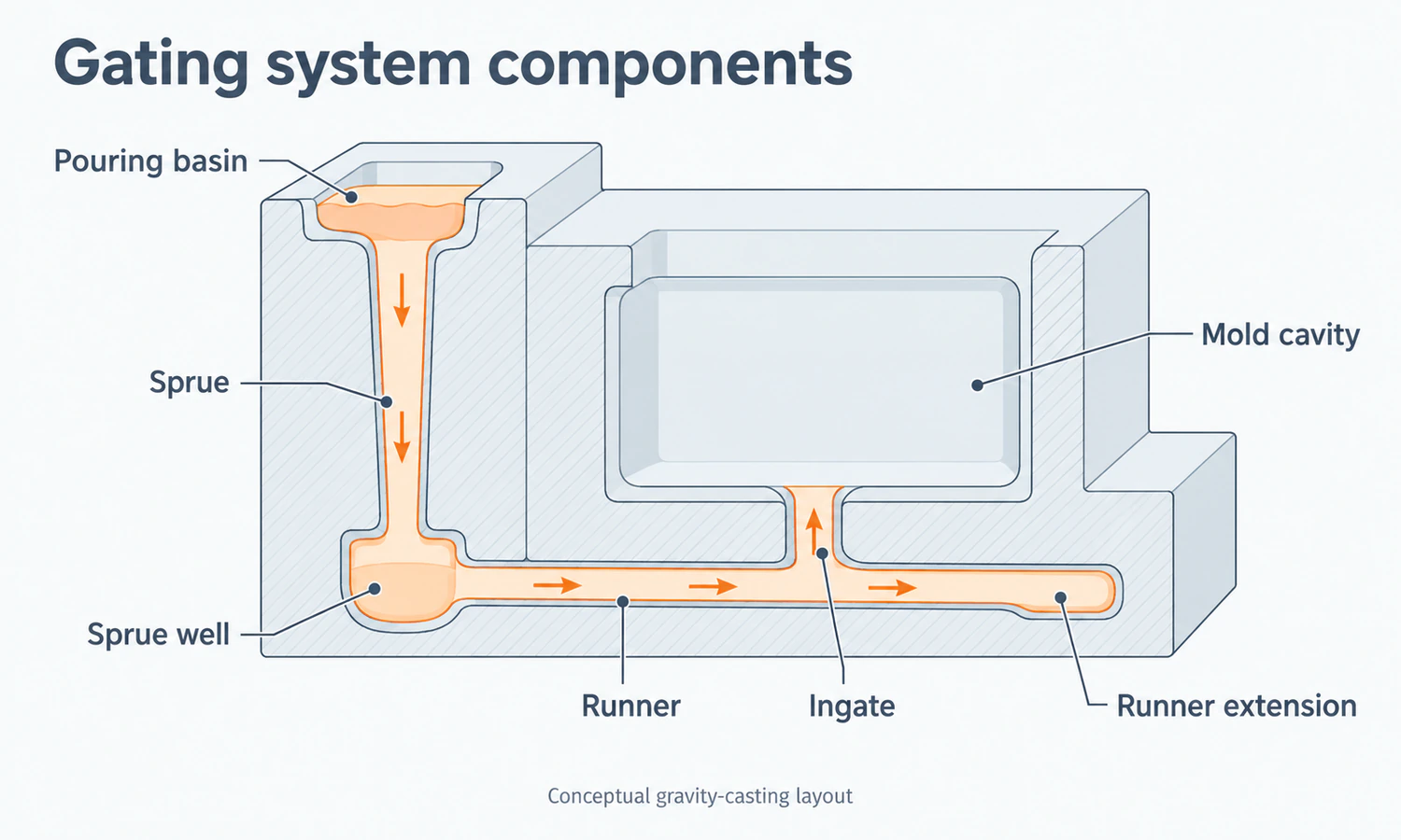
A gating system in casting is the network of passages that carries molten metal from the pouring point into the mold cavity. In a typical gravity-filled mold, that path may include a pouring basin or cup, a vertical sprue, a sprue well, one or more runners, and gates or ingates leading into the part.
The route looks simple on a drawing, but it controls one of the shortest and most consequential stages of production. Metal must reach every section before it freezes, yet excessive speed, splashing, abrupt turns, or unstable free surfaces can entrain air, create oxide films, erode a sand mold, or carry inclusions into the casting. A useful design therefore balances fill time, flow stability, temperature, cleanliness, feeding, metal yield, and the work required to remove the gates later.
That balance is why no gating ratio, gate velocity, sprue taper, or choke location works for every casting. Alloy behavior, part geometry, wall thickness, mold material, pouring height, equipment, and acceptance requirements all change the answer.
What Belongs in a Casting Gating System?
Terminology varies across foundries and references. The American Foundry Society metalcasting glossary distinguishes gates and runners from feeders or risers and vents. Other sources use gating system more broadly, or use rigging for the combined gating and feeding arrangement. This article uses gating or filling system for the passages that deliver metal to the cavity, and feeding system for the reservoirs and paths that supply liquid metal during solidification.
With that boundary established, the main gravity-casting components are easier to follow:
| Component | Primary function | What its design can influence |
|---|---|---|
| Pouring basin or cup | Receives metal from the ladle and directs it into the sprue. | Entry stability, metal head, dross carryover, and the effect of variations in the pour. |
| Sprue | Carries metal downward from the basin. | Acceleration, aspiration risk, flow rate, and the condition of metal reaching the runner. |
| Sprue well | Receives the descending stream at the base of the sprue. | Impact, direction change, energy dissipation, and entry into the runner. |
| Runner | Distributes metal horizontally or through branches. | Flow balance, travel distance, temperature loss, inclusion separation, and gate supply. |
| Runner extension or trap | Provides space beyond a gate or branch for the first metal and entrained material. | Capture of some cold metal, dross, slag, or loose particles; effectiveness depends on layout and flow. |
| Gate or ingate | Connects the runner to the casting cavity. | Entry velocity and direction, impingement, fill-front movement, gate mark, and removal work. |
| Choke | Provides the smallest effective flow area in the system. | Overall flow rate, back pressure, passage filling, and distribution between branches. |
| Filter, when used | Captures selected particles and modifies flow before the metal reaches the cavity. | Cleanliness, pressure loss, priming, temperature, and local flow behavior. |
Not every mold contains every item in this form. A direct gate may create a much shorter path, an investment-casting tree organizes several castings around a central passage, and a high-pressure die-casting system uses a shot sleeve, runners, gates, overflows, vents, and sometimes vacuum. The names matter less than understanding the job each feature performs in its actual process.
Metal Must Fill the Mold Quickly Without Losing Flow Control
Two failure directions define the basic design problem. If filling is too slow for the alloy, wall section, flow length, and mold temperature, the leading metal can lose fluidity before the cavity is complete. The result may be a misrun, an unfilled edge, or a cold shut where two partially solidified fronts meet without joining properly.
If the flow is unnecessarily fast or poorly directed, a jet can strike the mold or core, a free surface can fold over itself, and air can become trapped. Reactive alloys may form new oxide films as fresh metal surfaces are exposed. In a sand mold, concentrated impact can also loosen grains or pieces of the mold and carry them into the part.
Bernoulli’s equation, continuity, and momentum principles help explain why velocity changes with metal head and passage area. Real filling is more complicated than ideal pipe flow, however. The metal has a moving free surface, loses heat, turns through junctions, interacts with oxide films and surface tension, and encounters resistance from the actual mold. Calculations establish a starting point; they do not remove the need to observe and validate the real process.
A Tapered Sprue Reduces the Risk of Air Aspiration
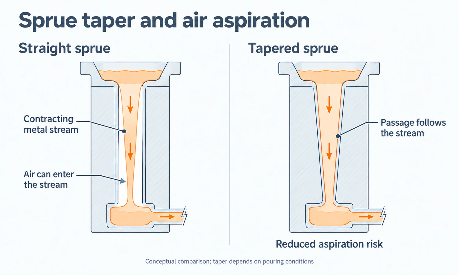
Metal accelerates as it falls through a vertical sprue. If the passage does not follow the contracting stream, the sprue may run partly empty and draw air into the flow. Gravity-casting sprues are therefore often tapered toward the bottom rather than made as straight cylinders.
The required taper is not a universal angle. It depends on the desired flow rate, pouring height, cross-sectional shape, entry condition, and the losses through the system. The sprue well and runner transition then have to turn the descending flow without simply moving the high-velocity impact to another surface.
Runner and Gate Layout Controls Where Flow Fronts Travel and Meet
A runner supplies one or more ingates, so its branch layout affects whether the gates receive metal at similar times and temperatures. Gate direction determines which mold surface the metal strikes, how far each front travels, and where separate fronts meet. Adding gates can shorten individual flow paths, but it can also create more meeting fronts, removal points, and opportunities for uneven distribution.
The most direct route is therefore not automatically the cleanest or easiest to finish. A gate placed on a functional surface may fill well but leave avoidable grinding or machining work. A route chosen only for easy cutoff may send metal through a longer, colder, or less stable path.
Gating and Risering Solve Different Problems
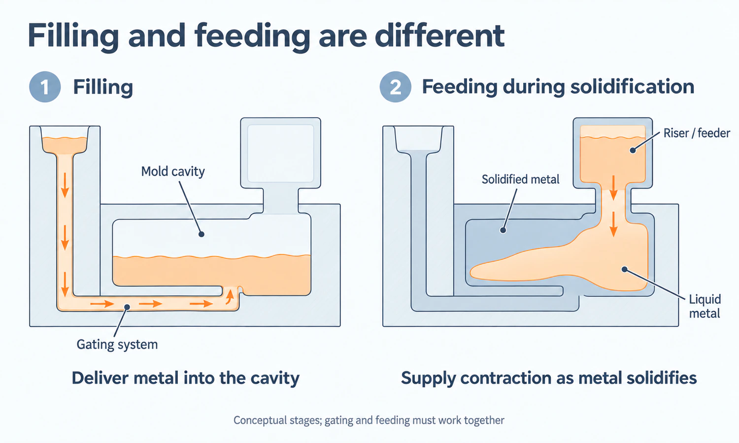
The gating system fills the cavity. A riser or feeder primarily supplies liquid metal as the casting contracts during solidification. Keeping those purposes separate prevents a common diagnostic mistake: treating every internal cavity as a gate problem or expecting an ingate to replace a properly designed feeding path.
The two systems still have to work together. Gates establish the initial temperature distribution and influence which regions begin to freeze first. Risers must remain connected to the areas they feed, and a narrow section that freezes early can isolate a hot spot even when the riser itself contains enough liquid metal. Chills, part orientation, section transitions, riser location, and gate location may all affect the same solidification sequence.
This interaction also changes gate removal decisions. A gate or feeder neck must remain effective long enough to perform its function, yet it eventually has to be cut or broken away without damaging the casting or leaving excessive finishing work.
Gating Ratio, Choke Area, and Fill Time Describe Different Controls
These three ideas are related, but they are not interchangeable. A ratio compares areas within the passage network. A choke identifies the smallest effective area that limits flow. Fill time describes how long the cavity takes to fill under the actual metal head, losses, alloy, and mold conditions.
Gating Ratio Compares Sprue, Runner, and Total Ingate Areas
A gating ratio is commonly written as the relative cross-sectional areas of the sprue, runner, and ingates. Before comparing two ratios, check the order of the terms and whether the gate value represents one gate or the total area of all gates. A ratio without those definitions can appear precise while describing two different systems.
Textbooks and foundries also classify ratios differently across alloys and processes. Copying a published ratio without its alloy, mold type, section geometry, metal head, and defect target removes the conditions that made the original choice meaningful.
The Choke Controls Overall Flow but May Sit in Different Locations
The choke is the system’s smallest effective flow section. Its area can limit the overall rate, while its position influences whether upstream or downstream passages remain full and how pressure develops through the branches. Depending on the process and design philosophy, the choke may occur near the sprue base, in the runner, or in the total ingate area.
Making one passage visibly smaller does not guarantee that it behaves as the intended choke. Junction losses, filters, partially filled runners, changing metal head, and uneven branches can shift the effective restriction during the pour.
Fill Time Balances Fluidity Against Flow Quality
A target fill time must be short enough to complete the cavity before critical sections freeze, but not selected only by asking how fast the mold can accept metal. Casting mass and volume, minimum wall, longest flow path, alloy fluidity, pouring temperature, mold temperature, available metal head, heat transfer, and gate removal requirements all influence the useful range.
The same number of seconds can represent very different conditions in a small thin aluminum casting, a thick steel casting, and a permanent-mold part. For that reason, an isolated fill-time or gate-velocity value should be treated as a project input to verify, not a universal specification.
Pressurized and Unpressurized Gating Use Different Area Progressions
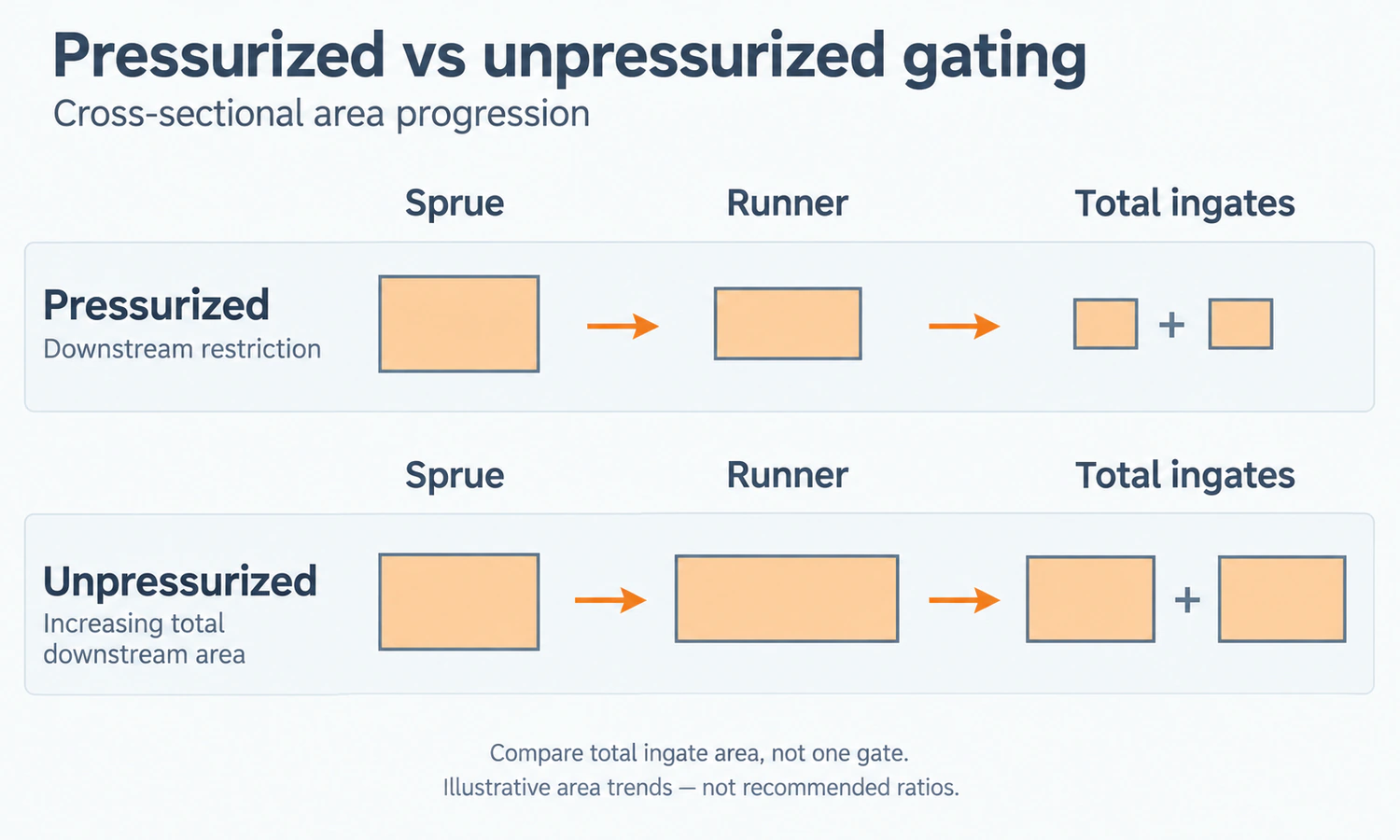
In common foundry usage, a pressurized system restricts the downstream flow area so passages tend to run fuller and develop back pressure. An unpressurized system expands the total downstream area, generally seeking lower local velocity. The names describe area relationships and flow behavior; they do not mean one system contains pressure like a sealed vessel while the other has none.
| System | Typical area trend | Potential benefit | Design risk to examine |
|---|---|---|---|
| Pressurized gating | Downstream restriction relative to the upstream passage. | Fuller passages, back pressure, and compact metal distribution in suitable applications. | Higher local velocity, mold or core impact, oxidation, and sensitivity to the restriction or branch balance. |
| Unpressurized gating | Increasing total flow area toward the ingates. | Lower local velocity and gentler entry where the arrangement remains well controlled. | Partly filled runners, unstable free surfaces, uneven distribution, or loss of intended flow control. |
Neither is universally superior. Alloy oxidation sensitivity, mold strength, runner orientation, number of gates, pouring consistency, cleanliness strategy, and the defects being controlled determine whether the area progression supports the part.
Gate Location Changes the Filling Pattern
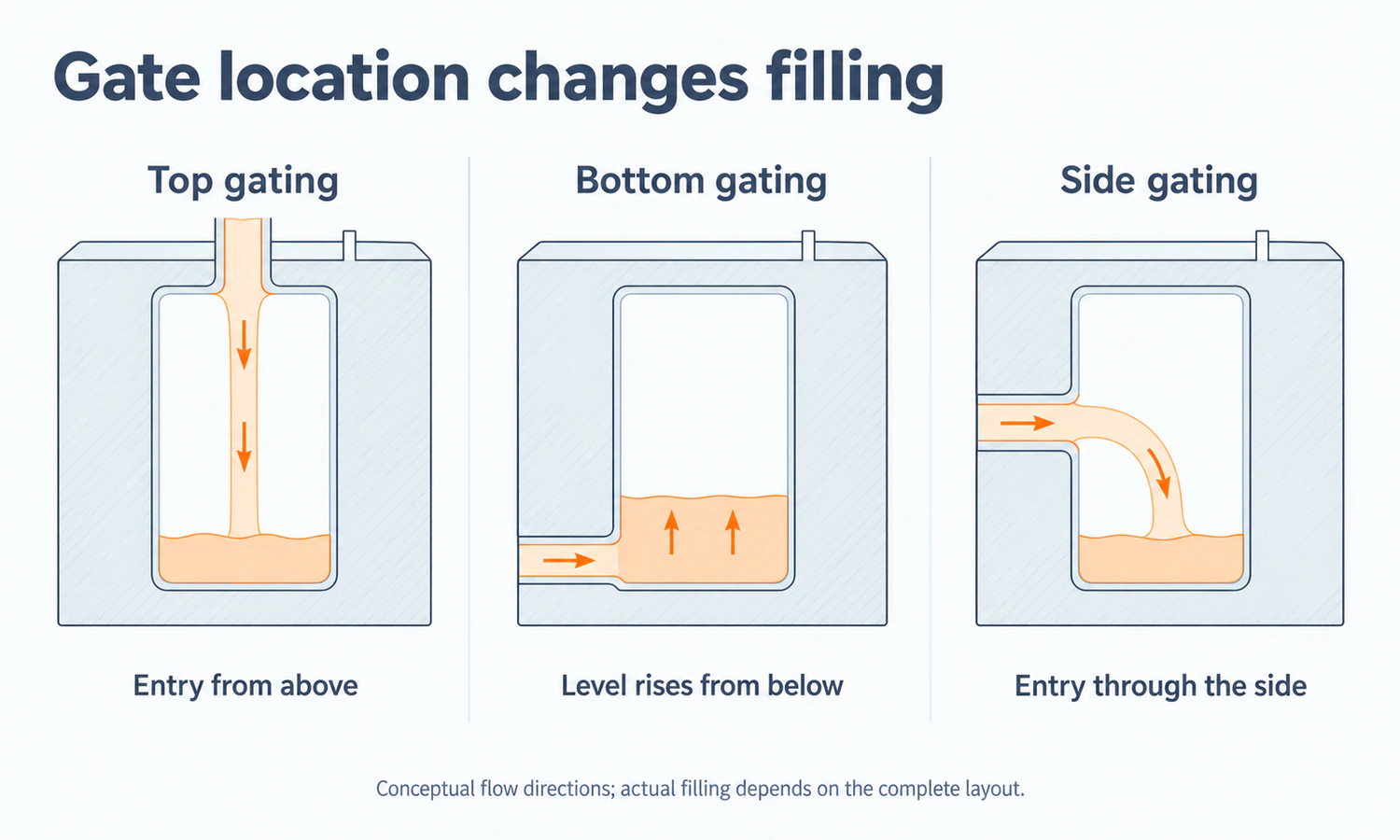
Top, bottom, side, parting-line, direct, and multiple gating describe where and how metal enters the cavity. Each arrangement changes travel distance, temperature loss, impingement, venting, flow-front meetings, feeding coordination, and the surface left after cutoff.
| Gate arrangement | How the cavity tends to fill | Questions the design must answer |
|---|---|---|
| Top gating | Metal enters high in the cavity and follows a relatively short path. | Will the falling stream splash, strike a core or mold face, entrain air, or disturb the desired solidification pattern? |
| Bottom gating | Metal enters low and rises through the cavity. | Will the longer route and heat loss still allow complete filling, and can air escape as the level rises? |
| Side or parting-line gating | Metal enters horizontally near the mold split or selected side feature. | Does the location suit molding, runner layout, core support, cutoff, surface finish, and flow distribution? |
| Direct gating | A short connection feeds the casting with few intermediate passages. | Can local impact, temperature, feeding interaction, and a concentrated gate mark be controlled? |
| Multiple gating | Several ingates shorten or divide the flow paths. | Will branches fill evenly, where will fronts meet, and how will every gate be removed and finished? |
The best location is the one that works with the actual orientation, parting line, cores, functional surfaces, and feeding plan. A label such as “bottom gated” cannot predict casting quality without the rest of that geometry.
How Gating Can Contribute to Casting Defects
Gating is one part of a connected process, so defect analysis should begin with evidence rather than a preferred correction. Defect location, shape, distribution, section thickness, melt records, pouring data, mold and core condition, and inspection results help separate several possible mechanisms.
Misruns and Cold Shuts Point to an Incomplete Filling Path
Metal may fail to reach an edge or thin section if the flow path is too long, the gates distribute metal unevenly, temperature falls too far, gas cannot escape, or the alloy loses fluidity before filling ends. Two fronts that arrive cold or carry persistent surface films may form a cold shut instead of joining fully.
Increasing pouring temperature or enlarging a gate can change the symptom, but either action may create new oxidation, gas, shrinkage, or mold-reaction problems. The review has to include the alloy, mold temperature, venting, section geometry, pouring consistency, and flow sequence.
Air Entrainment and Oxide Films Develop at Unstable Free Surfaces
Splashing, jetting, abrupt turns, and partially filled passages can expose and fold the metal surface. Air pockets may become trapped, while oxide films or dross can be carried into the cavity. A filter can capture selected particles and modify the flow, but it cannot replace clean melting and transfer practice or guarantee that no new film forms downstream.
Mold Erosion and Sand Inclusions Follow Local Impact and Mold Condition
A high-velocity stream aimed at a weak mold or core surface can loosen sand and carry it into the casting. Gate direction and local velocity matter, but so do sand strength, compaction or cure, coating, pattern withdrawal, core handling, and pouring temperature. Moving a gate without checking the damaged surface may only move the erosion site.
Shrinkage Requires a Feeding and Solidification Review
Gating can influence the temperature field, but shrinkage forms when solidification contraction is not adequately fed. The diagnosis must consider riser performance, hot spots, section transitions, chills, feeding distance, and whether a connecting section froze too early. Our sand casting defects guide explains why gas, oxide, sand, and shrinkage indications need different evidence paths.
Gating Rules Change with the Casting Process
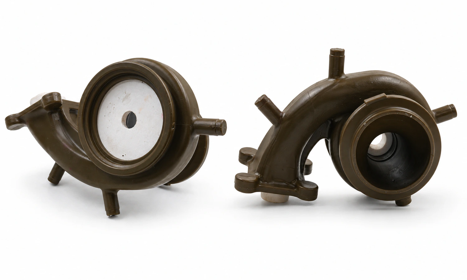
The broad aim remains controlled and complete filling, but the equipment and mold change how that aim is achieved.
| Casting process | Gating context | Process-specific concerns |
|---|---|---|
| Sand casting | Typical gravity flow through sprues, runners, and ingates in an expendable sand mold. | Mold and core erosion, permeability and venting, parting-line layout, sand inclusions, and removal from the casting. |
| Investment casting | Wax patterns are assembled with gates around a central tree or cluster, then replaced by passages in a ceramic shell. | Cluster balance, shell filling, thin sections, metal and mold temperature, cutoff, and feeding within the assembly. |
| Permanent-mold casting | Gravity fills a reusable metal mold through designed runners and gates. | Rapid heat extraction, mold coating and temperature, venting, filter placement, cycle consistency, and early freezing. |
| High-pressure die casting | A shot system drives metal through runners and thin gates at high speed, with overflows, vents, or vacuum supporting cavity filling. | Shot profile, air evacuation, gate velocity, thermal balance, die erosion, overflows, and solidification under pressure. |
A ratio or velocity developed for one row should not be copied into another. Even within sand casting, a steel casting and an aluminum casting may require different approaches because fluidity, oxidation behavior, pouring temperature, density, heat transfer, and mold interaction differ. The wider sand casting process guide shows how the gating system fits with the pattern, cores, mold, pouring, shakeout, and finishing stages.
Casting Yield Measures Metal Use, Not Quality by Itself
Casting yield is commonly calculated as the weight of acceptable castings divided by the total poured metal that becomes castings, gates, runners, and risers. It helps show how much metal produces saleable parts and how much returns to remelting, but a higher percentage is useful only if the casting still fills, feeds, and meets its acceptance criteria.
Consider a hypothetical mold that produces 6 kg of acceptable casting from 10 kg poured, with 4 kg in gates, runners, and risers. Its yield is 60%. If a validated redesign produces the same acceptable 6 kg casting with 3 kg of non-product metal, the yield becomes 66.7%, an increase of 6.7 percentage points. The calculation is simple; proving the redesign is better requires more evidence.
If the lighter system increases misruns, inclusions, shrinkage, process variation, or gate-removal damage, the apparent metal saving can be consumed by scrap, rework, inspection, and schedule disruption. Yield, defect rate, finishing labor, remelt energy, and stable production therefore belong in the same cost review.
Gating Design Develops Through Calculation, Simulation, and Trials
A practical workflow narrows the design in stages. It begins with the part and process rather than a favorite ratio.
Initial Sizing Establishes the Flow Path
The designer gathers alloy data, casting mass and volume, wall sections, flow lengths, orientation, mold and core properties, pouring height, temperature conditions, target fill behavior, feeding layout, equipment limits, gate-removal surfaces, and inspection zones. Flow and heat-transfer calculations, established foundry rules, and past results then provide an initial sprue, runner, gate, and choke arrangement.
Simulation Compares Flow and Solidification Alternatives
Computational fluid dynamics and solidification tools can compare fill fronts, local velocity, air entrainment, temperature distribution, hot spots, and shrinkage tendency. They are especially useful when several layouts would be expensive or slow to test physically.
A simulation is still a model. Material properties, heat-transfer coefficients, boundary conditions, pouring input, mesh, vent assumptions, and defect criteria influence the result. A smooth animation does not by itself prove that the mold will fill cleanly or that a production line will repeat the event.
Trial Castings Verify the Production System
Trial pours connect the model to the real mold, metal, operator or pouring equipment, and process variation. Fill evidence, temperature or time records, sectioning, radiography, computed tomography, penetrant testing, dimensions, defect maps, and yield data may be used according to the risk and expected discontinuity.
Validation should answer the project question: does this layout repeatedly produce the required part under the proposed production conditions? If tooling, alloy, orientation, pouring practice, or acceptance criteria change, the earlier result may need another review.
Information Required to Review a Casting Gating System
A supplier can discuss a gating problem more precisely when the request includes the finished-part requirements and the evidence already available. Useful inputs include:
- 2D drawings, a 3D model, or a physical sample, including parting-line and core constraints if known;
- alloy, material specification, casting weight or volume, critical walls, and longest flow paths;
- expected batch and annual quantity, molding process, pouring equipment, and tooling status;
- critical surfaces, machining stock, gate-removal restrictions, and final surface requirements;
- riser, chill, vent, filter, or existing gating information when reviewing a current design;
- NDT method, inspection zones, acceptance criteria, reports, and traceability requirements;
- for an existing defect, its exact location, morphology, frequency, photographs, sectioning or inspection results, and matching melt, mold, and pouring records.
YTD Foundry provides custom investment casting, sand casting, and die casting, together with tooling, CNC machining, inspection, surface finishing, and finished-part delivery. We evaluate the manufacturing route from the drawing, material, geometry, quantity, functional surfaces, and acceptance requirements so that filling, feeding, machining, and inspection support the same finished component.
A Good Gating System Is Specific to the Casting
A gating system succeeds when it delivers sufficiently clean metal to every part of the cavity within the available thermal window and does so repeatably under production conditions. It must also work with the risers and solidification path, preserve the mold, leave removable connections, and use metal efficiently.
No single feature proves that result. A tapered sprue can reduce aspiration risk, a filter can capture selected particles, a bottom gate can support a rising fill, and simulation can reveal likely problem areas. Each remains part of a larger system whose performance depends on the alloy, mold, geometry, equipment, and process controls.
The most reliable design is therefore not the one with the most familiar ratio or the fastest calculated fill. It is the one whose assumptions are explicit and whose filling, defect, feeding, yield, and finishing results have been verified for the actual part.