What Is the Typical Tolerance Range That Investment Casting Can Achieve?
A 1962 Investment Casting Institute design article gives a practical investment casting tolerance range of about ±0.003 to ±0.005 in. per inch of dimension. This is a useful early screening range, but it is not an ISO table, a YTD Foundry guarantee, or a value you can copy directly into a drawing.
Tolerance simply means the permitted variation from a target dimension. The real question is not only “How accurate is investment casting?” It is whether a particular feature, in a particular material and final condition, can be cast and inspected within the required limits.
The following sections take one continuous path: read the number correctly, understand why it changes, use a standard as a shared language, choose an as-cast, straightened, or machined route, and give the foundry enough information to confirm the project.
How Should You Read a Typical Investment Casting Tolerance?
Read a typical value as a screening tool, not as proof that a finished part will comply. You first need to identify the target dimension, the permitted variation, the unit, and the condition in which the part will be measured.
What the number means on a drawing
Suppose a drawing shows an illustrative dimension of 25.00 ±0.10 mm. The nominal dimension is 25.00 mm, while the acceptable range is 24.90 to 25.10 mm. The ± value describes the permitted dimensional variation; it does not describe surface finish, flatness, repeatability, or the accuracy of the entire process.
The historical ICI range uses an inches per inch format. For an illustrative 4 in. dimension, ±0.003 to ±0.005 in./in. gives an early screening range of ±0.012 to ±0.020 in. The controlled length matters, so the same per-inch expression produces a larger absolute deviation on a longer dimension.
Why a practical range is not a guarantee
The ICI value comes from an older industry design article. The source itself explains that material, size, and configuration change achievable results. It also warns that unnecessarily tight requirements add cost. That makes the value useful for an early conversation, not for final acceptance.
Keep four evidence levels separate when you review a number:
- Industry rule of thumb: a broad screening reference such as the historical ICI range.
- Standard baseline: a common way to specify general requirements.
- Supplier capability: what a foundry can hold for the relevant material, geometry, tooling, process, and production condition.
- Drawing requirement: the value and inspection method accepted for the specific project.
Before you use any tolerance chart, check its source and date, nominal-size range, unit, manufacturing state, and whether the listed number is a total tolerance band or a bilateral ± value. If the heading does not make that clear, do not convert or apply the number by assumption.
Why Does Tolerance Change From One Feature to Another?
Investment casting does not produce one accuracy level for every feature. The controlled span, geometry, material, pattern route, final condition, and measurement setup all change the result.
Size and geometry change the type of risk
A longer dimension can accumulate more variation than a short one. That is why a per-inch rule may help with an initial linear-dimension check.
Geometry adds different risks. Thin or long sections, broad flat areas, asymmetric shapes, and abrupt section changes may bend or distort in ways that a linear formula cannot describe. When you review a drawing, look beyond the overall part size and identify the span and shape of each functional feature.
Material, route, and final condition change the answer
Tooling and pattern production establish the starting geometry. Pattern cooling, assembly, shell building, metal solidification, heat treatment, cut-off, and any later straightening can then change dimensions or shape. The article does not need a full process history to make the practical point: the stage at which you inspect the part must be stated.
Material grade and heat-treatment condition also matter. A result measured before heat treatment should not automatically be treated as the final delivery condition. Likewise, a prototype made by one pattern route does not by itself prove stable capability for a different production route.
Dimensional and geometric controls answer different questions
A linear dimension can be within limits while the part still has a form or orientation problem. For example, a flange thickness may be acceptable even though the mounting surface is not flat enough or is not parallel to another functional surface.
Flatness controls the form of a surface and does not use a datum reference. Parallelism controls a relationship to a datum. If a geometric relationship affects assembly, sealing, location, or inspection, define the appropriate control, reference, support condition, and measurement method instead of trying to solve it with a tighter linear dimension.
What Does ISO 8062 Help You Specify?
ISO 8062-3:2023 provides a shared language for general dimensional tolerances, the geometrical tolerances listed in its scope, and machining allowance grades for castings. It can help a buyer and foundry start from the same reference, but it cannot prove that a supplier can hold a particular requirement on a particular part.
Online guides often use CT grade as informal shorthand for a general casting tolerance grade. The shorthand does not replace the current standard’s exact notation, and the grade does not automatically cover every critical feature or the finished dimensions created by machining.
If your drawing uses a general casting tolerance, cite the full standard and year, use the correct designation from the standard, and identify the units and final manufacturing condition. Mark function-critical dimensions and geometric controls individually when a general note is not enough.
The standard provides a specification baseline. The foundry still has to compare that baseline with its process capability for the alloy, tooling, geometry, quantity, and inspection method. Final acceptance should come from the mutually approved drawing and purchase requirements, not from a blog table.
Should This Feature Be As-Cast, Straightened, or Machined?
Choose the route feature by feature. Start with function, then consider distortion risk, access for machining, reference and inspection needs, and the cost of validation.
As-cast means the feature reaches its required condition without dimensional machining. Straightened or controlled means an agreed post-casting operation is used to correct or stabilize a distortion-prone feature. Machined means material is intentionally left and later removed to create the final size or surface. That extra material is a machining allowance, not a permitted dimensional error.
| Feature or functional need | Reasonable starting path | What to confirm |
|---|---|---|
| Noncritical envelope or clearance feature | Evaluate as-cast | General tolerance, final condition, and inspection point |
| Long, thin, broad, or distortion-prone feature | Evaluate controlled casting or straightening | Permitted correction, fixture or gauge, applicable references, and condition at inspection |
| Bearing fit, sealing face, thread, precise location, or other critical finished surface | Evaluate machining | Finished requirement, machining allowance, access and setup, responsibility, and inspection method |
This table is a decision aid, not an absolute rule. A feature can remain as-cast only when the supplier confirms that route for the material, geometry, quantity, and acceptance method. Machining may provide better final control, but it also adds stock, setups, time, inspection, and responsibility that must be included in the quote.
For YTD projects, casting accuracy for small and medium-sized parts is typically about ±0.1 mm, with the actual result depending on part size and process difficulty.
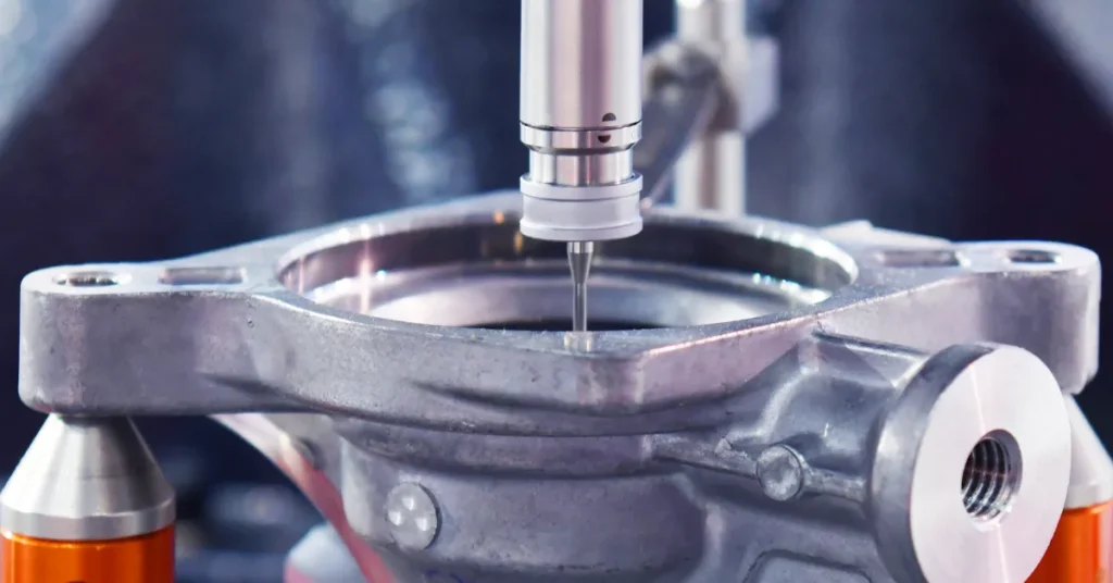
YTD’s in-house CNC machining accuracy is 0.05 mm; this is an accuracy statement, not automatically a bilateral ±0.05 mm tolerance. Ultra-high-precision machining in the 0.02–0.01 mm range and CMM inspection are available through partner suppliers and require project-specific confirmation.
What Should You Send the Foundry for a Reliable Tolerance Answer?
Send enough information to connect each critical feature to its function, final condition, manufacturing route, and acceptance method. A typical-value table cannot replace this project package.
- 2D drawing and 3D model: identify the current revision and mark the features that control fit, sealing, location, load transfer, or later machining.
- Material and final condition: state the alloy grade and the required heat-treatment or delivery condition.
- Critical requirements: separate general dimensions from individually controlled dimensions, geometric tolerances, surfaces, and assembly interfaces.
- Manufacturing responsibility: state which features should be evaluated as-cast, which may be straightened, and which party will machine the finished features.
- Machining allowance and references: define the stock, access, setup, and any datum or reference scheme required by the selected control.
- Quantity and project stage: distinguish prototypes, samples, and expected production quantities because validation and tooling decisions may differ.
- Inspection: agree on the measurement method, support or fixture condition, sampling, and required reports before quotation. If CMM inspection is needed for a YTD project, its partner-supplied scope should also be confirmed.
Ask the foundry to confirm the proposed route and any exceptions in writing. That confirmation should say which features are accepted as-cast, which require a controlled correction, which will be machined, and when each requirement will be inspected.
Your next step is simple: mark the features that control function, state the final condition and inspection requirements, and send the package for a part-specific review. YTD can evaluate a combined route using its in-house tooling, silica-sol investment casting, and CNC capabilities, with partner-supplied services where required. Visit the investment casting service page to start that evaluation.