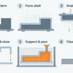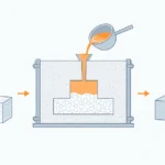
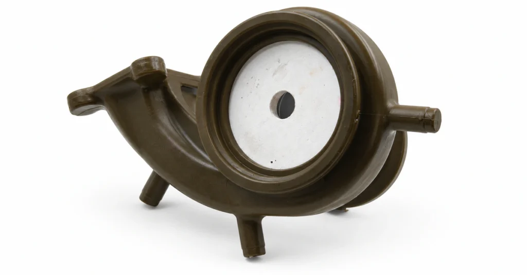
In the usual metal-pouring sense, cores in casting occupy the spaces where molten metal must not go. A foundry places a shaped core inside the mold, pours metal around it, and removes or withdraws the core after solidification. The surface of the core becomes an internal surface of the casting, allowing the process to form holes, chambers, cooling passages, pump channels, undercuts, and recesses that the main pattern cannot create or release by itself.
Sand cores are the most familiar example, but they are not the only kind. Investment casting may use ceramic cores for intricate internal passages, some high-pressure die-casting systems use expendable salt cores, and permanent molds may use reusable metal cores that can be withdrawn. The material, manufacturing method, support arrangement, and casting process all affect what a core can do.
A core adds design freedom, but it also adds tooling, handling, positioning, gas, dimensional, cleaning, and inspection work. The important question is therefore not simply whether a cavity can be cored. It is whether the core can be made, supported, filled around, removed, and verified reliably.
Casting Cores Form Internal Surfaces the Pattern Cannot Release
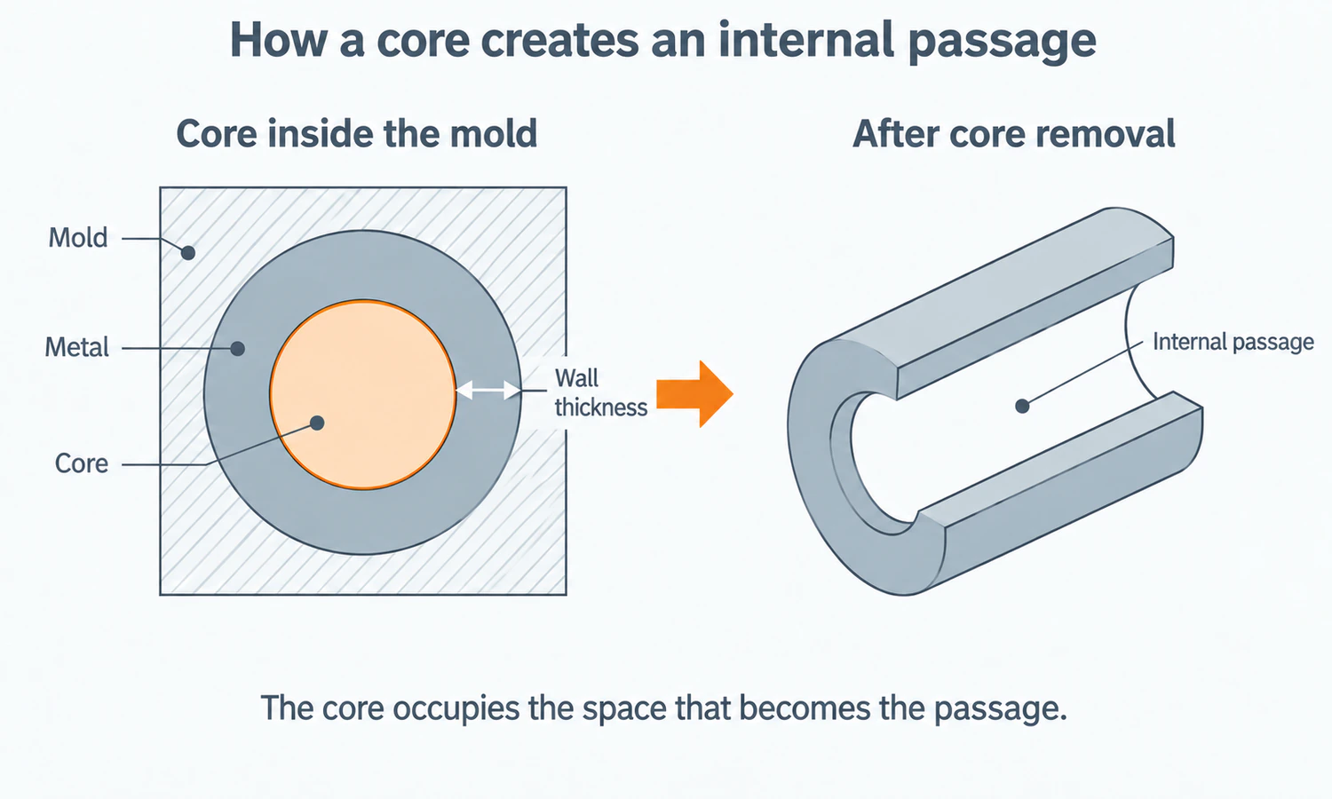
A pattern forms an impression in the molding material and establishes the main mold cavity. The mold surrounds the space that will receive metal. A core sits inside that cavity and displaces metal from selected regions. The gap between the mold surface and the core surface becomes the casting wall.
Several related terms describe different objects, and keeping them separate makes the rest of the process easier to understand. The American Foundry Society metalcasting glossary provides the industry definitions behind these distinctions.
| Term | What it is | What it does |
|---|---|---|
| Pattern | The form used to create the main impression in molding material. | Defines much of the casting’s external geometry and may include core prints. |
| Mold | The body containing the cavity that will be filled with metal. | Forms the outer boundary of the poured shape. |
| Core | A separate preformed shape placed within or against the mold cavity. | Forms internal surfaces or features the pattern cannot release. |
| Core box | The tool used to shape a conventional sand core. | Defines the core geometry before it is cured and placed in the mold. |
| Core print | A projection on the pattern that leaves a locating and bearing seat in the mold. | Positions and supports the core during mold assembly and pouring. |
| Chaplet | A small metal support used where core prints alone are insufficient. | Helps hold the core and remains embedded in the finished casting. |
| Cast-in insert | A functional piece intentionally left in the casting. | Becomes part of the product rather than being removed like a core. |
A core does not have to create a fully enclosed cavity. It may form a side recess, undercut, port, or local contour that would lock the pattern into the mold. That broader definition is useful when deciding whether to core the feature, change the parting line, machine it after casting, or redesign the part.
When a Casting Needs a Core
A core is a strong candidate when an internal feature must be present as cast and cannot be produced by the normal pattern withdrawal. Manifolds, valve bodies, pump housings, water jackets, impellers, and other flow components often contain geometry that leads designers to consider cores. The product name alone, however, does not prove that a particular casting uses one.
Coring can replace extensive drilling, machining, joining, or plugging, especially when the passage curves, branches, or changes section. It can also reduce the amount of solid metal in a part. Those benefits have to be weighed against the added core box or printing cost, coremaking, assembly, setting, removal, inspection, and risk of variation.
Reducing the number of cores can simplify production when the function allows it. A different parting line may let the mold create a surface directly. Two similar cores may be combined into one assembly, or a difficult passage may be redesigned for better support and cleanout. In other cases, machining a straight hole or splitting the product into joined sections is more controllable than trying to cast a long, inaccessible passage.
Core Prints Position and Support the Core
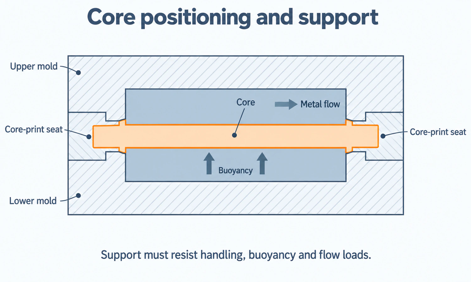
A conventional sand core usually extends into seats left by core prints. These seats establish the core’s position and provide bearing area during mold assembly and pouring. Their geometry influences setting clearance, support direction, resistance to rotation, and whether gases or spent core material have a route out of the casting.
Too much clearance can allow movement or inconsistent location. Too little can damage the core during setting or prevent the mold from closing. A print that supports the core under handling loads may still be inadequate once liquid metal surrounds it, because the core then faces buoyancy, flow impact, heat, and changing strength.
Buoyancy and Metal Flow Can Move or Break a Core
Molten metal produces an upward force on a core that displaces it, while the filling stream can bend or strike unsupported sections. Long, slender, cantilevered, or unevenly supported cores are more sensitive to these loads. Core material, length and diameter, surrounding metal section, print arrangement, gate direction, and pouring conditions all affect the result.
Reinforcement, extra prints, altered orientation, or a different filling path may improve support, but each choice has consequences for removal, gas flow, tooling, and the casting surface. There is no universal core length-to-diameter limit that covers every alloy and mold.
Chaplets Add Support but Remain in the Casting
When ordinary core prints cannot hold a core in the required position, chaplets may provide additional support or spacing. They are made of metal and remain in the casting after the pour, so they must become suitably incorporated into the surrounding metal.
Incomplete fusion, contamination, placement error, or different thermal behavior can create a local discontinuity. A chaplet is therefore an engineered support with its own material, location, process, and inspection requirements, not a risk-free substitute for an inadequate core-print design.
Sand-Core Materials Must Balance Opposing Properties
A sand core usually combines a refractory aggregate with a binder, a catalyst or hardener where the system requires one, and selected additives. Silica sand is common, while zircon, olivine, chromite, and engineered ceramic media may be chosen when thermal expansion, refractoriness, density, surface, or alloy reaction calls for a different aggregate.
No single material is best across all castings. The core has to survive manufacturing, storage, handling, setting, mold closing, and pouring, then become removable after the metal has solidified. Some of the required properties pull in opposite directions.
| Core property | Why it matters | The balance to maintain |
|---|---|---|
| Handling and hot strength | Prevents damage before pouring and resists buoyancy, impact, and erosion during filling. | Excessive strength can make decoring harder or restrain casting contraction. |
| Permeability | Allows gases generated in or around the core to move toward an escape path. | A more open structure may change strength and the metal-core surface interaction. |
| Low gas generation | Reduces the gas load that must escape while metal surrounds the core. | Binder chemistry, amount, cure, moisture, coating, and pouring temperature all contribute. |
| Refractoriness and thermal stability | Helps the core resist heat, expansion, softening, and reaction with the alloy. | Aggregate and binder choices also affect cost, density, surface, and removal. |
| Dimensional stability | Preserves the intended passage and wall thickness through cure, storage, and pouring. | Shrinkage, humidity, coating, assembly, and thermal deformation can change the core after tooling. |
| Collapsibility | Lets the casting contract and allows the core to break down during cleaning. | A core that collapses too early may erode, distort, or fail during the pour. |
| Surface and erosion resistance | Helps produce a usable internal surface without loose grains or excessive penetration. | Grain size, coating, permeability, gas, and metal flow must remain compatible. |
This is why adding more binder is not a universal route to a better core. It may increase a selected strength measurement while also changing gas evolution, permeability, thermal breakdown, reclamation, and the work needed to clean the casting.
The Sand-Core Manufacturing Process
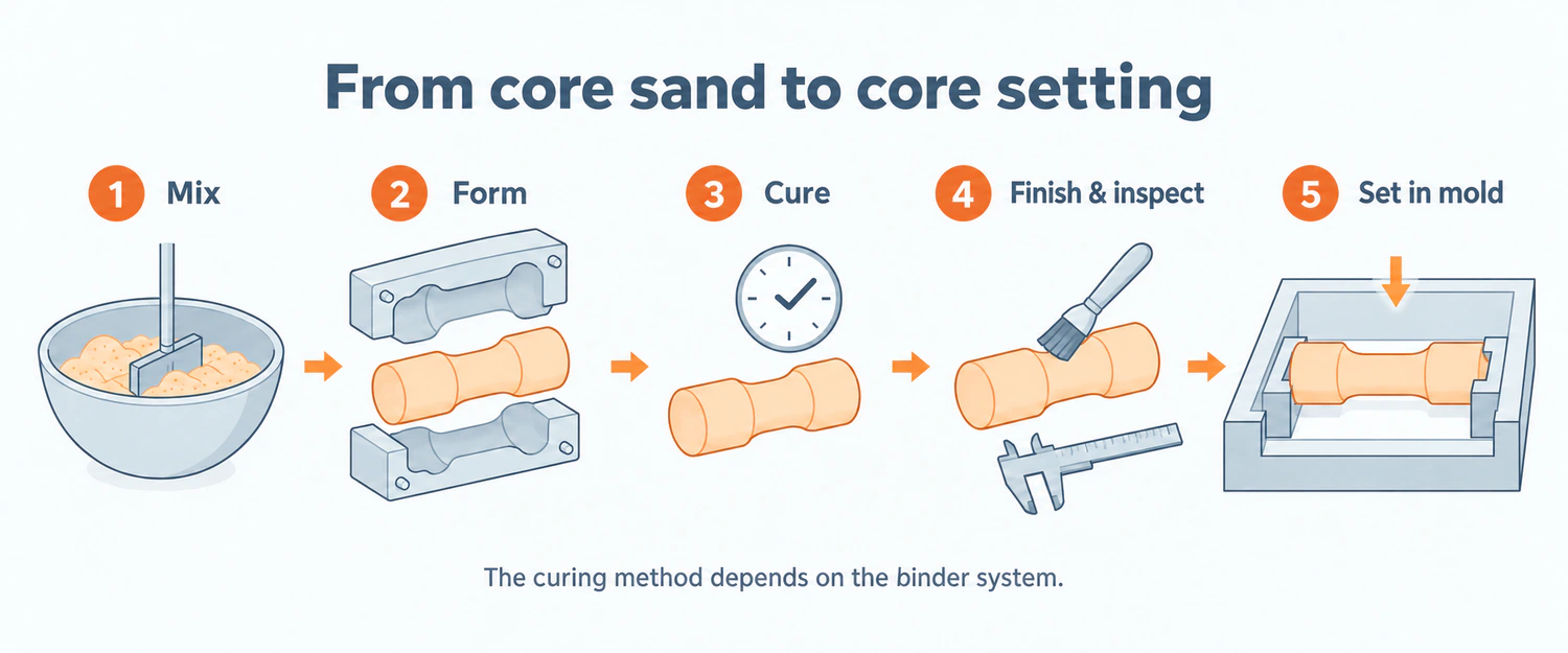
Coremaking turns loose aggregate and binder into a dimensionally controlled form that can be handled and placed in the mold. The exact sequence varies with the binder and equipment, but the broad production path is consistent.
1. Aggregate, Binder, and Additives Are Mixed
The foundry prepares the sand and binder system for the alloy, core geometry, curing route, surface requirement, storage time, and pouring conditions. Mixing has to distribute the binder without creating uncontrolled strength, gas, or variability. Moisture and temperature may also matter, depending on the chemistry.
2. The Core Box Forms the Geometry
Prepared core sand is blown, shot, rammed, or otherwise placed into the core box. Wood, resin, plastic, or metal tooling may be used according to size, complexity, expected quantity, curing process, accuracy, and tool life. Split boxes, loose pieces, multiple cavities, and ejection features help release shapes that a simple one-piece box cannot produce.
Draft and parting decisions still matter in conventional core boxes because the cured or partially cured core must leave the tool without tearing or distortion. Binder-jet printed sand cores remove the dedicated core box, but they do not remove the need to support, depowder, handle, inspect, and cast the core.
3. Curing Gives the Core Its Handling Strength
The filled core box may be heated, exposed to a catalyst gas, or left to cure at room temperature, depending on the binder system. Cure has to reach the intended section without leaving weak regions, excessive brittleness, dimensional change, or residues that interfere with coating and pouring.
4. Finishing, Assembly, Coating, and Inspection Prepare the Core
After ejection, the core may be trimmed, repaired, joined to other core pieces, coated, dried, gauged, and stored. Multi-piece assemblies can form passages that one core box cannot release, but their joints introduce mismatch, fins, adhesive, accumulated dimensional error, and another place where gas or metal may travel.
5. Core Setting, Pouring, and Decoring Complete the Cycle
The finished core is placed in its prints or other supports, checked, and enclosed when the mold closes. Metal fills the space between mold and core. After solidification, the core is broken down, withdrawn, dissolved, or otherwise removed, and the internal surfaces are cleaned and inspected as the specification requires.
Cold-Box, Hot-Box, Shell, No-Bake, and Silicate Systems
Names such as cold-box and hot-box describe binder and curing routes. They do not describe whether the core is horizontal or vertical, and they do not define the shape it produces. The U.S. EPA foundry emissions protocol lists several established coremaking families because their chemistry, curing, and emission behavior differ.
| Coremaking system | How the core hardens | Variables that need control |
|---|---|---|
| Cold-box | A catalyst gas rapidly cures a resin-bonded core in an unheated or low-temperature box. | Gas distribution, binder chemistry, purge, cure depth, ventilation, storage, and breakdown. |
| Hot-box or warm-box | Heat from the core box cures the binder system. | Tool temperature, filling, cure time, section thickness, release, energy, and dimensional stability. |
| Shell core | Resin-coated sand cures against heated tooling to form a rigid shell. | Shell thickness, tool temperature, dump or fill behavior, cure, surface, and production quantity. |
| No-bake or airset | A binder system and its hardener or catalyst cure at room temperature without heated tooling. | Mix ratio, working time, strip time, ambient conditions, gas, strength, and reclamation. |
| Sodium silicate/CO2 | Carbon dioxide hardens a sodium-silicate-bonded sand system. | Gas exposure, cure uniformity, strength, moisture, breakdown, and sand recovery. |
| Oil-bake and other oven-cured systems | Heat in a separate oven cures an oil- or resin-based binder. | Baking cycle, emissions, energy, handling, strength, and collapsibility. |
The table describes process families, not universal recipes. Commercial binders within one family can use different catalysts, additions, temperatures, cure times, and controls. These values belong to the selected material system and verified foundry process.
Core Coatings Protect the Surface but Must Remain Permeable and Dry
A core wash is a refractory coating applied to the core and dried before pouring. It can improve the metal-core contact surface and help resist penetration, erosion, burn-on, or reaction. Coating may also help seal repaired areas or joints when the material and procedure allow it.
More coating is not automatically better. Thickness, solids, carrier, application, drying, adhesion, and permeability have to suit the core and alloy. A wet, cracked, poorly bonded, or overly restrictive coating can introduce gas, flaking, dimensional, or cleanout problems. The coating complements aggregate, binder, gating, venting, and pouring control rather than correcting every weakness underneath it.
Core Venting Gives Binder and Mold Gases an Escape Path
Heat from the metal releases gas from binders, coatings, moisture, and other constituents. Permeable core structure, vents, and routes through core prints can help that gas move away before pressure builds at the metal interface. Long blind passages and cores surrounded by thick hot metal can be more difficult to vent than a short core with openings at both ends.
Gas-related porosity is still not proof of a core problem. Dissolved gas in the melt, air entrained by the gating system, mold gas, temperature, and solidification may produce similar or overlapping indications. Diagnosis requires the location and morphology of the pores together with core batch, binder, coating, vent, melt, pouring, and inspection records.
Core Shift, Breakage, Gas, and Expansion Defects
Core-related defects often appear in the casting, but the underlying event happened earlier during coremaking, storage, assembly, setting, mold closing, or pouring. Four groups are especially useful during investigation.
Core Shift Changes Opposing Wall Thicknesses
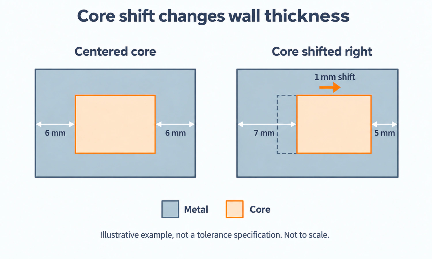
Core shift occurs when the core moves from its intended position or when parts of a core assembly are misaligned. A simplified centered section shows why a small movement matters: if both walls are designed to be 6 mm and the core shifts 1 mm sideways, one wall becomes 5 mm while the opposite wall becomes 7 mm. The external casting size may remain correct even though the internal passage and two walls are displaced.
Those numbers are an illustration, not a general allowance. Core-print fit, setting accuracy, assembly joints, buoyancy, metal impact, mold alignment, core strength, and thermal deformation can all produce the observed variation. Measurements across several sections help distinguish whole-core movement from local bending or a core-box problem.
Core Breakage and Erosion Leave Sand or Obstructions
A weak, damaged, or poorly supported core may crack before pouring or break under metal flow. Surface grains can also erode and become sand inclusions. The passage may change shape, partially block, or contain loose material after cleaning. Strength is part of the diagnosis, along with handling, core age, coating, gate direction, local velocity, and mold closing.
Veining, Penetration, and Burn-On Begin at the Metal-Core Interface
Thermal expansion and stress within a sand core can open cracks that fill with metal and create veins or fins. Metal may also penetrate between grains or form an adherent layer that is difficult to remove. Aggregate expansion, grain distribution, binder, additives, coating, pouring temperature, metal pressure, and alloy reaction all influence these surfaces.
A defect name identifies what to inspect, not the one adjustment to make. Our sand casting defects guide explains how gas, sand, oxide, and shrinkage evidence should be separated before changing a mold or melt process.
Removing the Core Is Part of Casting Design
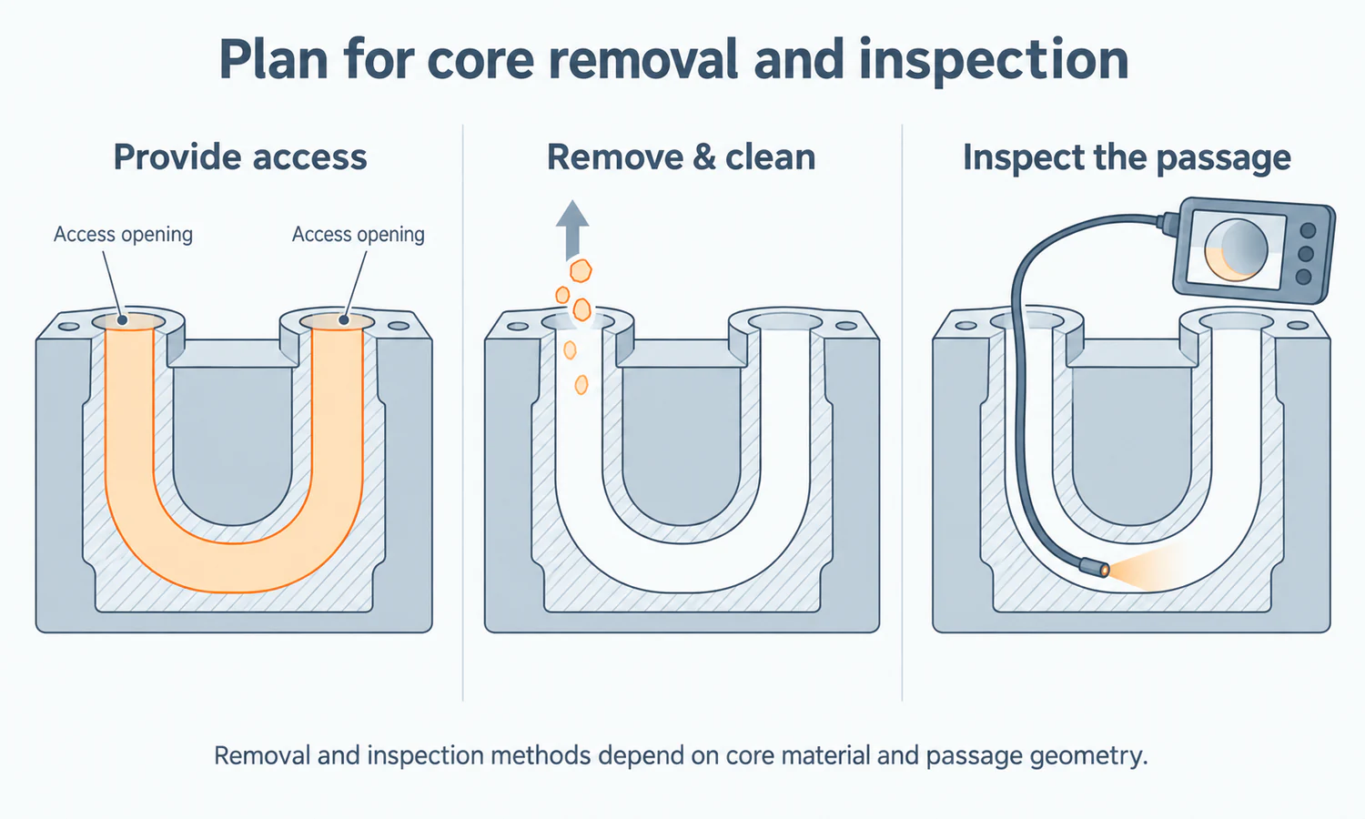
An expendable core has not finished its job when the casting solidifies. It must release as the metal contracts and then leave the passage without damaging the part or leaving unacceptable residue. Shakeout, vibration, mechanical cleaning, blasting, water jetting, thermal breakdown, dissolution, or chemical leaching may be used according to the core material, alloy, channel, and cleanliness requirement.
Long, narrow, curved, blind, or branching passages make removal harder because tools and broken core material have fewer routes in and out. The drawing should provide adequate openings and identify areas that must be free of loose sand, coating, or leaching residue. A passage that can be cast but cannot be cleaned or inspected is not yet a production-ready design.
Internal cleanliness also needs an acceptance method. Visual checks may work near an opening, while a borescope, flushing or extraction procedure, flow test, pressure test, sectioning, radiography, or computed tomography may be needed for other geometries. No single method proves that every internal surface is absolutely free of residue or discontinuities.
Sand, Ceramic, Wax, Salt, and Metal Cores Serve Different Processes
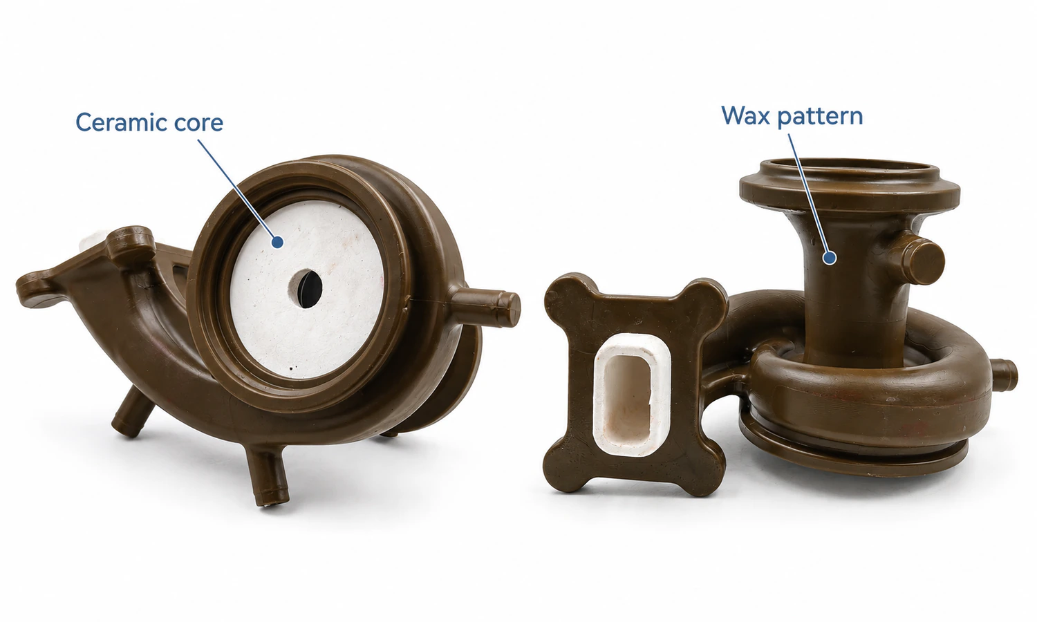
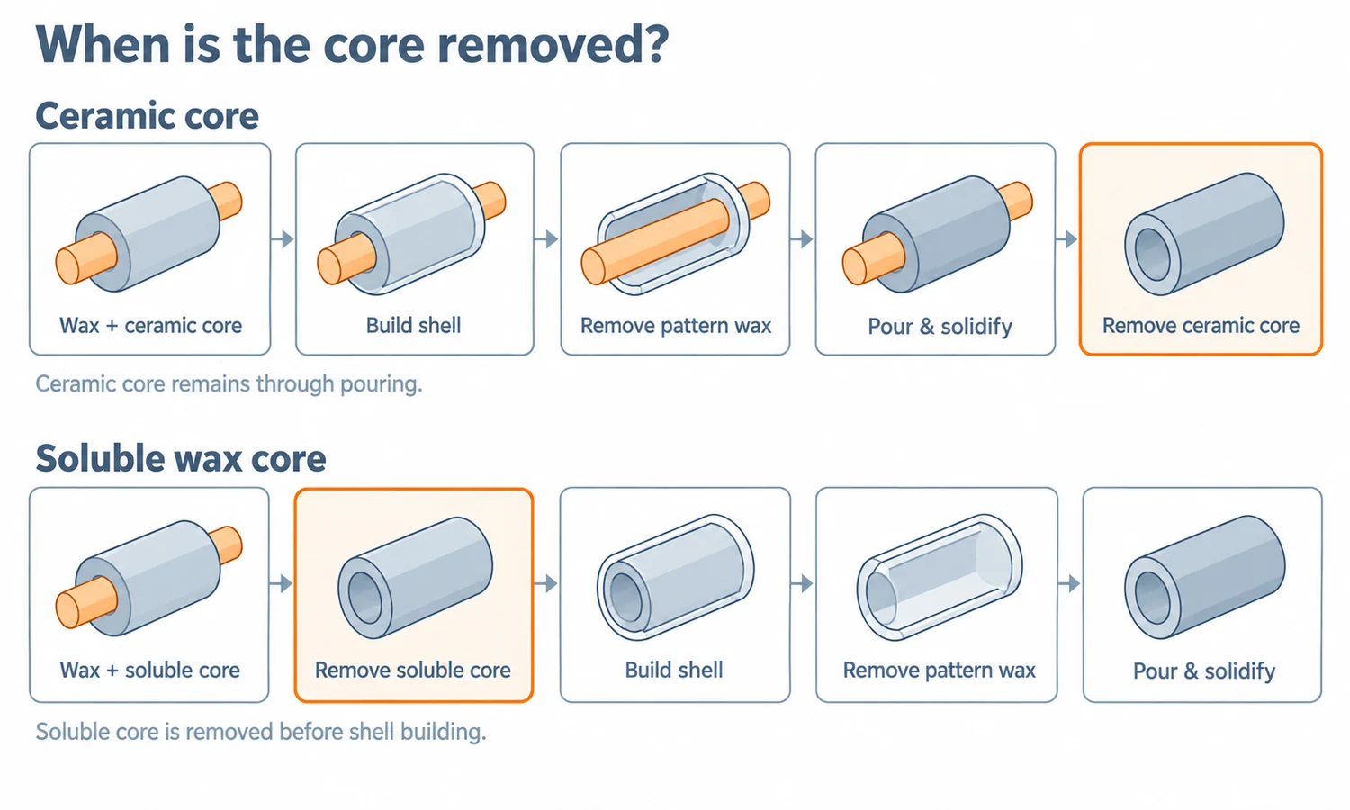
Core types are often presented as one long list, but the names may describe material, manufacturing route, or position. The clearest comparison is what occupies the empty space, when it is present, and how it leaves the part.
| Core type | Typical casting context | How it functions and leaves |
|---|---|---|
| Bonded-sand core | Common in sand casting and used in selected permanent-mold arrangements. | Aggregate and binder form the internal shape; the core breaks down and is cleaned out after solidification. |
| Ceramic core | Complex internal passages in investment casting. | The core survives wax processing, shell building, and metal pouring, then is removed by an appropriate mechanical or leaching route. |
| Soluble wax core | Formation of an investment-casting wax pattern with accessible internal surfaces. | Pattern wax is formed around the soluble wax, which is removed before shell building and never faces molten metal. |
| Expendable salt core | Specialized hollow geometry in selected high-pressure die castings. | A strong salt form survives high-pressure filling and is dissolved after casting under a validated process. |
| Metal core | Permanent-mold or selected die-casting designs with a withdrawal path. | A reusable core forms the feature and is mechanically withdrawn, requiring draft, release, thermal control, and suitable geometry. |
A positional term such as horizontal, vertical, balanced, hanging, or cover core describes how a core sits or is supported in a sand mold. It can overlap with a material and process description. A vertical cold-box sand core, for example, combines a support orientation, a curing method, and a material family; these are not three competing core types.
3D-Printed Sand Cores Change Tooling, Not the Engineering Requirements
Binder jetting builds a sand core layer by layer by selectively depositing binder into a sand bed. It can eliminate a dedicated core box and make internal shapes that would otherwise require several conventional cores and assembly joints. This can be valuable for prototypes, low quantities, design changes, and highly connected passages, and the method has also entered production applications.
Printing does not make the core tool-free in the wider manufacturing sense. Digital preparation, build orientation, printing, depowdering, curing, coating, handling, setting, casting, removal, and inspection still require a controlled route. Research on 3D-printed furan core and molding sands shows that binder content, grain, permeability, friability, and thermal behavior have to be considered together.
Higher binder saturation or a denser printed structure may improve selected strength results while reducing permeability or increasing gas generation. Lower binder can help another property but leave the core too fragile for handling and pouring. Performance depends on the printer, sand, binder chemistry, layer thickness, orientation, cure, storage, geometry, and alloy, so one research percentage should not be copied into an unrelated production specification.
Core and Cored-Feature Inspection Answer Different Questions
Before pouring, a foundry may check core dimensions, mass or density, strength, permeability, moisture, gas evolution, friability, coating coverage, assembly location, damage, and storage condition. The exact test plan depends on the core system and the risk. The AFS Mold & Core Test Handbook provides standardized industry procedures across aggregates, chemically bonded sands, and coatings.
After casting, inspection shifts to the resulting metal feature. Dimensional layout or CMM can check accessible geometry, a borescope can inspect reachable surfaces, and radiography or CT can reveal selected internal conditions. Leak, pressure, and flow testing answer functional questions under defined test conditions. Sectioning can expose geometry and defects directly but destroys the sample.
These methods do not replace one another. A correct flow rate does not prove wall thickness, a radiograph does not automatically establish internal cleanliness, and one section cannot prove every production casting. The drawing or purchase specification should define the critical zones, method, coverage, sampling, reporting, and acceptance criteria.
Coremaking Safety Depends on Sand and Binder Chemistry
Coremaking can involve respirable dust, heated tooling, catalyst gases, solvents, and binder or coating emissions during mixing, curing, pouring, cooling, and cleaning. Organic systems may release volatile organic compounds, hazardous air pollutants, or thermal decomposition products, while inorganic systems have different handling and breakdown concerns. The actual safety plan must follow the selected product’s safety data, process, ventilation, capture equipment, and local requirements.
When silica-bearing sand is used, mixing, core finishing, shakeout, and cleaning can create respirable crystalline silica exposure. OSHA identifies foundry sand as an occupational silica source and links exposure with silicosis, lung cancer, chronic obstructive pulmonary disease, and kidney disease. Material substitution, enclosure, local exhaust ventilation, housekeeping, monitoring, training, and protective equipment have to be selected for the actual operation.
Information Required for a Cored Casting Quote
A useful DFM review begins with the finished internal feature instead of a preferred core recipe. Provide the available 2D drawing, 3D model, or physical sample, together with:
- alloy, casting process, heat treatment, operating temperature, and corrosion or pressure conditions;
- internal passage geometry, openings, blind ends, branches, minimum walls, and critical datums;
- which surfaces may remain as cast and which will be machined, sealed, coated, or joined;
- internal surface, residual-sand, cleanliness, flow, leak, and pressure requirements;
- sample, batch, and estimated annual quantities, including the expected life of conventional tooling;
- inspection method, coverage, acceptance criteria, reports, and traceability requirements;
- functional limits on changing the parting line, enlarging cleanout openings, machining a feature, or splitting the design.
YTD Foundry provides custom investment casting, sand casting, and die casting, together with tooling, CNC machining, inspection, surface finishing, and finished-part delivery. We evaluate the route from the drawing, material, internal geometry, quantity, functional surfaces, and acceptance requirements so the mold, cores, machining, cleaning, and inspection support the same finished component.
A Core Is Successful Only If It Can Be Removed and Verified
The best core is not simply the strongest one or the one that creates the most intricate cavity. It holds the intended geometry through production, survives the thermal and mechanical loads of pouring, works with the required gas-control path, and then collapses, dissolves, or withdraws through a practical route.
That complete path changes how an internal feature should be designed. Core prints and supports must control location, openings must permit cleaning, the process must leave enough wall where the core can move or deform, and inspection must be able to verify the requirement that matters to the part.
A casting core expands what can be made as one component, but it does not remove the need to compare machining, parting-line changes, split assemblies, or another casting process. The right choice is the one that produces the required internal geometry repeatedly and leaves a casting that can be cleaned, inspected, and delivered in its specified condition.