A thick boss can remain liquid after the surrounding casting has frozen, leaving shrinkage inside an otherwise complete part. A chill helps control when that region solidifies. Its effectiveness depends on where it removes heat—and whether replacement metal can still reach the shrinking section.
What Is a Chill in Casting?
A chill is a heat-absorbing insert used to accelerate solidification in a selected part of a casting. It is often a metal block placed against the mold cavity, although other shapes and internal arrangements are also used.
In a sand mold, a metal chill extracts heat more rapidly than the surrounding sand. This changes the local freezing sequence without requiring the entire mold to be metal.
The name describes its function; it does not mean the insert must be refrigerated. The aim is controlled heat removal during casting, not cooling the finished component afterward.
Chill manufacturer Smith & Richardson identifies shrinkage control and directional solidification as their purposes. Directional solidification means arranging the freezing sequence so that regions still needing feed metal remain connected to a liquid supply.
How Do Chills Help Prevent Shrinkage?
When a region contracts during solidification, it needs replacement liquid metal. If the surrounding metal freezes first and cuts off that supply, a shrinkage cavity or interconnected porosity can develop.
A chill helps by making a selected region freeze earlier. Used with a suitable feeding system, it encourages solidification to progress toward the feeder instead of leaving an isolated pocket of liquid inside the component.
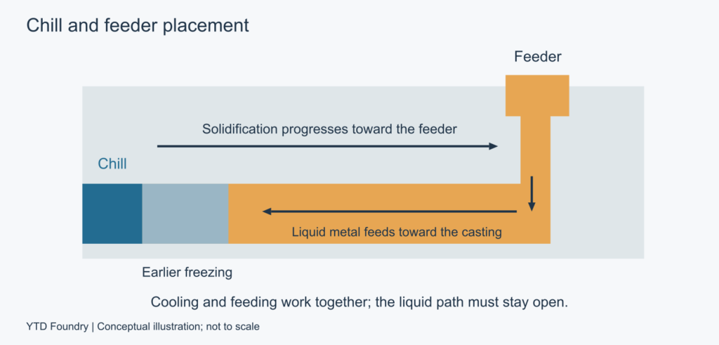
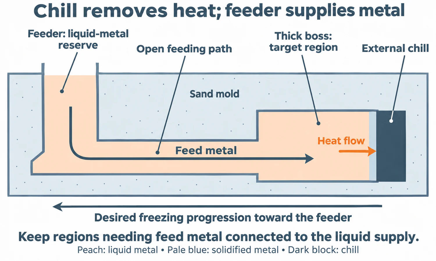
Consider an illustrative layout: a plate has a thick boss at its far end and a feeder near the other end. The boss may solidify late because it contains more metal relative to its cooling surface. A chill against the boss can help it freeze sooner, while the connecting section remains able to supply metal.
However, cooling the connecting section first could isolate the boss. The same additional cooling that helps in one location can cause a feeding problem in another.
Track where the last liquid remains and how it receives feed metal. The layout below illustrates cooling the remote end while retaining a connection to the feeder.
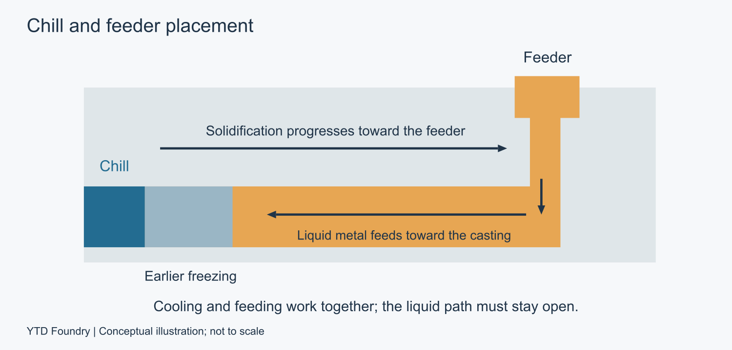
Conceptual section, not to scale. The arrows describe the intended relationship; the actual freezing sequence needs validation.
Internal and External Chills
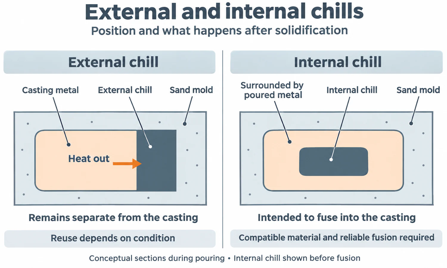
The main distinction is whether the chill becomes part of the casting.
| Feature | External chill | Internal chill |
|---|---|---|
| Position | At the outside boundary of the casting, usually forming part of the mold cavity surface | Within the cavity, surrounded by poured metal |
| After solidification | Remains separate from the casting | Is intended to fuse with and become incorporated into the casting |
| Main application concern | Heat transfer through the contact surface | Compatible composition and reliable fusion |
| Reuse | Can be reused if its condition remains suitable | Is consumed in the casting |
External chills make it possible to cool a surface-accessible region without leaving an insert inside the component. Internal chills bring the cooling effect into a location that an external block may not reach effectively.
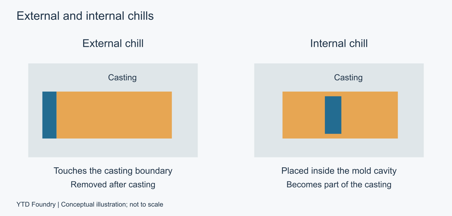
Schematic sections. The internal insert is shown before incorporation into the solidified casting.
An internal chill is therefore a metallurgical choice as well as a thermal one. Poor fusion or contamination at its interface can create an internal discontinuity. Its material, surface preparation and dimensions must suit the alloy and pouring conditions. Sundo’s aluminum casting guidance explains this distinction and the additional fusion requirements of internal chills.
Chills, Risers, and Chaplets
These features can appear in the same mold, but they have different primary jobs.
| Feature | Main job | What it controls |
|---|---|---|
| Chill | Extract heat locally | Where and when metal solidifies |
| Riser, or feeder | Supply additional liquid metal | Compensation for solidification shrinkage |
| Chaplet | Support or locate a core | Core position and the resulting cavity geometry |
A chill does not provide the reserve of molten metal that a riser provides. It can improve the feeding arrangement, but it cannot automatically replace the feeder.
Equally, a larger feeder cannot help an isolated hot spot if the path between them freezes shut. A successful layout needs both adequate feed metal and a usable route to the region requiring it. Our guide to risers in casting explains that relationship in more detail.
Chaplets may also influence local cooling because they are metal inserts, but supporting the core remains their defining function. A drawing should identify which function each insert is intended to perform.
What Materials Are Chills Made From?
Cast iron and steel are common external chill materials. Copper and graphite are also used in suitable applications. Material selection involves more than choosing the highest thermal conductivity.
Three properties of the arrangement matter together:
- Heat transfer rate: How quickly heat moves from the casting into and through the chill.
- Heat capacity: How much heat the chill can absorb as its temperature rises.
- Contact conditions: How effectively heat crosses the interface between the casting and chill.
A small, highly conductive insert can heat up quickly and lose much of its initial cooling effect. A larger block of another material may continue absorbing heat for longer.
This distinction appears in an original study by Sugiyama and colleagues, published in 1957. The abstract of Heat Absorbance of Mold and the Soundness of Casting, Report 2, listed in volume 29, issue 2, pages 108–116, reports that, for equal dimensions in their tests, copper chills initially absorbed heat faster than steel chills, but the relationship later reversed. That finding supports comparing performance over the required solidification period, rather than ranking materials by conductivity alone.
The interface also changes during cooling. A coating adds thermal resistance, and contraction can create a gap between an external chill and the casting. A simulation that assumes perfect contact throughout may overestimate the cooling effect.
Where Are Chills Placed?
Chills are placed where earlier solidification will improve the overall feeding sequence. Areas worth investigating include thick bosses, heavy wall junctions and sections far from a convenient feeder.
An end chill acts at the end of a casting section. A drag chill is positioned in the lower half of the mold, often between feeding regions. These names describe location; either arrangement still needs to be evaluated with the surrounding geometry and feeders.
For a practical review, follow the metal’s needs through the layout:
- Identify the region that remains liquid longest.
- Determine which feeder supplies it and through which section.
- Evaluate whether local chilling improves that sequence without closing the feeding route too early.
- Check filling as well as solidification, especially where metal must pass through a thin section.
For the plate-and-boss example, the comparison should include the original layout, a chill at the boss and any necessary feeding changes. The result to look for is a connected, feedable solidification sequence. Moving the predicted shrinkage from the boss into another functional area would not solve the problem.
How Is Chill Size Chosen?
Chill size depends on the alloy, section geometry, contact area and feeding arrangement. Published ratios are useful only within their stated conditions.
For its low-alloy steel plate-section rules, the SFSA’s 2001 Feeding & Risering Guidelines recommends an end-chill thickness between one-half and two-thirds of the casting section thickness, T. Chill thickness is measured perpendicular to the contact face.
For an illustrative 30 mm section, that gives:
30 × 0.5 to 30 × 2/3 = 15–20 mm chill thickness.
The same guidance reports about 19% greater end-effect feeding distance, using a multiplier developed with a chill thickness of 2T/3. This is a feeding-distance result, not a 19% reduction in defects.
It also warns that a drag chill wider than about 2T can produce porosity above the chill. See SFSA’s guidelines, pages 32–34.
These figures illustrate why increasing chill size indefinitely is ineffective. They are specific steel-casting guidance, not universal dimensions for aluminum, cast iron or investment castings.
What Problems Can Chills Cause?
Moisture, Contamination, and Movement
A chill must arrive at the pouring stage in a clean, dry and securely located condition. Rust and contamination can introduce problems, while movement changes the intended contact and cooling location.
In its guidance on placing chills in large molds, ASK Chemicals also highlights condensation and the effect of cold inserts on sand-binder curing. Preparation must suit the molding process; there is no single preheating temperature that applies to every chill and alloy.
Incomplete Filling and Feeding Problems
Excessive local cooling can make metal freeze before a thin section fills, or prevent meeting streams from joining properly. It can also freeze a feeding connection too early.
These outcomes need different corrections. An incompletely filled edge points toward a filling problem; shrinkage inside a fully formed boss points toward solidification and feeding. Adding another chill without identifying the mechanism may make matters worse.
Hard Areas in Cast Iron
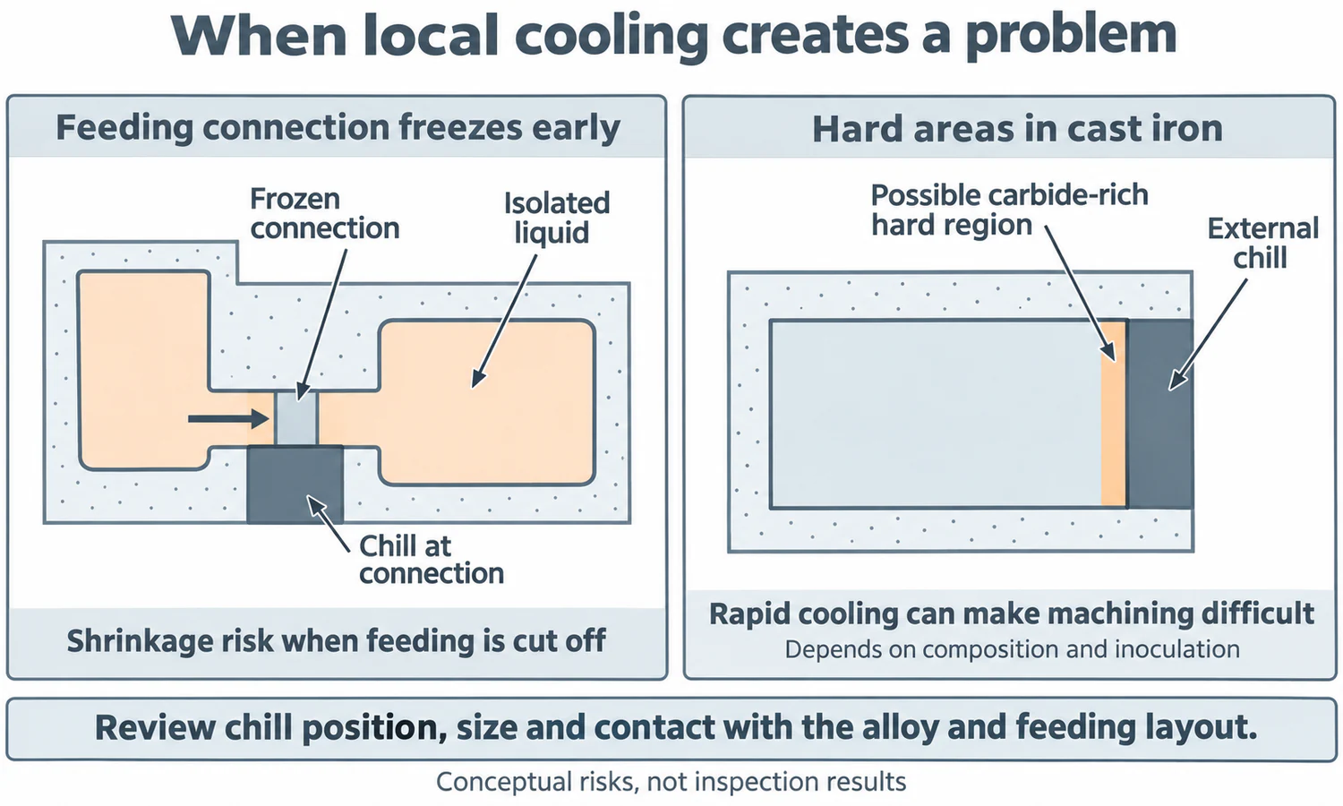
In cast iron, rapid cooling can promote hard carbide-rich regions when conditions favor white-iron formation. Such areas can make machining difficult. Cooling rate must therefore be considered alongside composition and inoculation.
Elkem’s explanation of inoculants describes how inoculation promotes graphite formation and reduces the tendency to form cementite, an iron carbide.
The terminology is easy to confuse: a casting chill is a cooling insert; chill in cast iron can mean a carbide-rich structure; a cold shut is a failure of metal streams to fuse properly. They are related to thermal conditions, but they are different things.
How Is a Chill Arrangement Verified?
Verification combines process analysis with inspection of actual castings.
Casting simulation can compare filling, freezing sequence, isolated liquid regions and predicted shrinkage for different layouts. The model needs realistic chill material, initial temperature, contact and coating assumptions. Compare the predictions with examination of the corresponding regions in trial castings.
Trial castings should then be checked at the region the chill was intended to improve—and at any location where the revised layout may have created a new problem. Depending on the part, useful checks include sectioning, radiography, ultrasonic examination or hardness and microstructure testing.
For shrinkage, examine the former hot spot internally. For a suspected hard chilled region in cast iron, check hardness and microstructure. Our overview of casting inspection methods explains the relevant methods.
Once the arrangement is validated, repeatability matters. Chill position, condition and preparation belong in the controlled production method, so the tested cooling arrangement can be reproduced.
Conclusion
Chills help control local solidification, while feeders supply replacement metal. Effective use requires the right position, size, material and contact conditions. The goal is a sound casting with a workable feeding sequence, confirmed by inspection—not simply faster cooling or a larger chill.
FAQs
What Is a Chill in Casting?
A chill is a heat-absorbing insert used to accelerate solidification in a selected part of a casting, often a metal block placed against the mold cavity. The name describes its function—it does not mean the insert must be refrigerated.
What Is the Difference Between a Chill and a Riser?
A chill extracts heat locally to control where and when metal solidifies. A riser supplies additional liquid metal to compensate for shrinkage. A chill does not provide the reserve of molten metal that a riser provides, so it improves the feeding arrangement rather than replacing the feeder.
What Is the Difference Between Internal and External Chills?
An external chill sits at the outside boundary of the casting, usually forming part of the mold cavity surface, and remains separate after solidification. An internal chill sits within the cavity, is surrounded by poured metal, and is intended to fuse into the casting—it is consumed and requires compatible composition and reliable fusion.
What Materials Are Chills Made From?
Cast iron and steel are common external chill materials, with copper and graphite used in suitable applications. Selection balances heat transfer rate, heat capacity, and contact conditions—a small, highly conductive insert can heat up quickly and lose its initial cooling effect.
Where Should Chills Be Placed?
Place chills where earlier solidification improves the overall feeding sequence: thick bosses, heavy wall junctions, and sections far from a convenient feeder. Check that the additional cooling does not close the feeding route too early or interfere with filling.
Can Chills Cause Problems?
Yes. Moisture, rust, contamination, or movement can create their own defects. Excessive local cooling can prevent thin sections from filling or freeze a feeding connection too early. In cast iron, rapid cooling can also promote hard carbide-rich regions that make machining difficult.