What is Shell Mold Casting
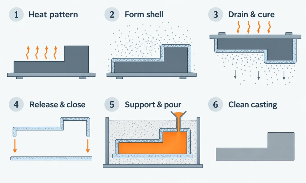
Shell mold casting is a sand casting process that uses a thin, rigid mold made from resin-coated sand. A heated metal pattern bonds a layer of sand into a shell. The shell is removed, joined to a matching half, and filled with molten metal. After the metal solidifies, the sand mold is broken away to release the casting.
The metal pattern is reusable; the sand mold is expendable. This arrangement allows the same tooling to produce many closely matching molds, making shell molding useful where repeated production, surface quality, and dimensional consistency matter.
Also known as shell molding, shell moulding, or the Croning process, it combines the flexibility of a disposable sand mold with the repeatability of metal tooling. Its value depends on whether those benefits justify making, heating, and operating the tooling for the part.
How Resin-Coated Sand Forms a Shell
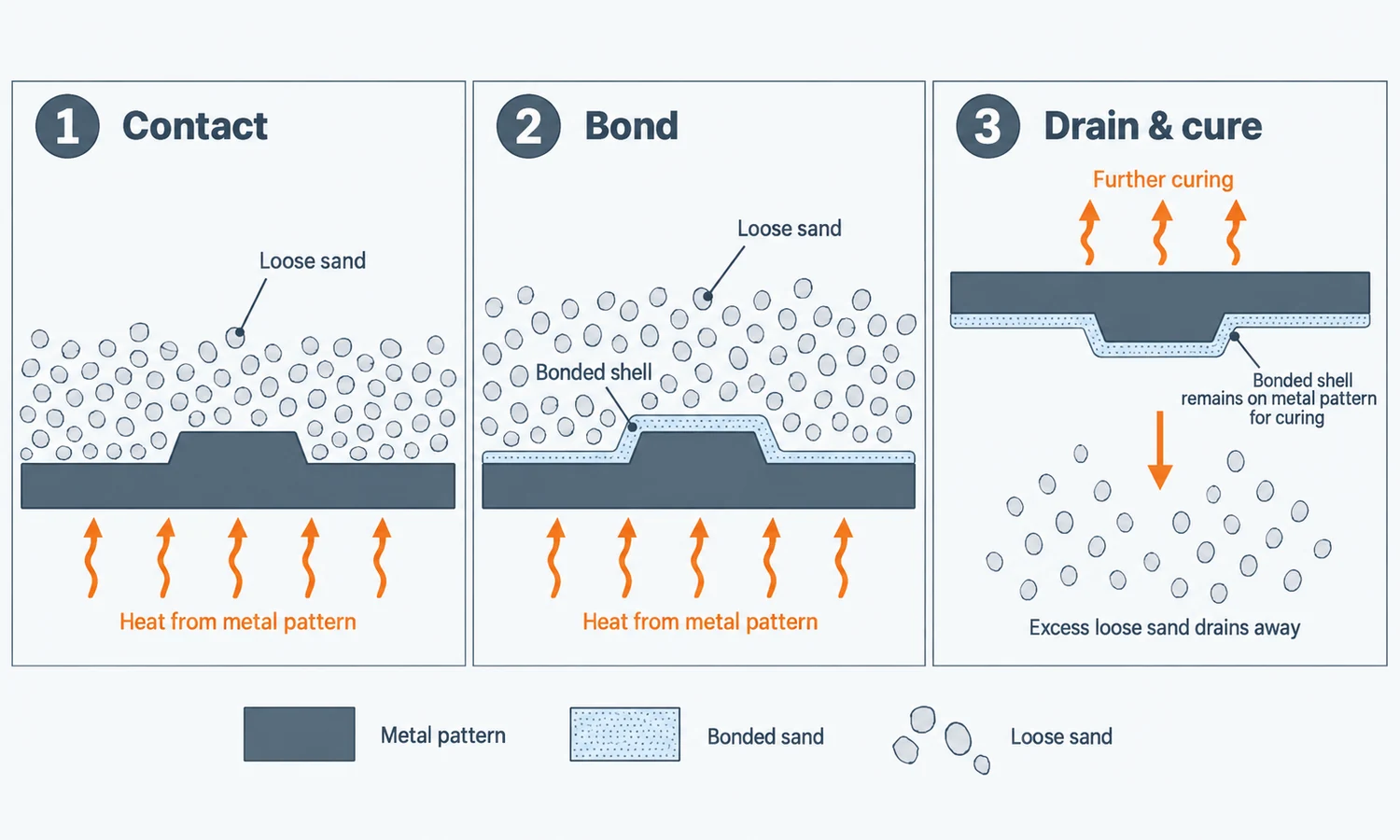
The sand used for shell molding is coated with a heat-activated resin that binds the grains together. Fine silica sand and phenolic resin are a common combination, although the aggregate and binder system vary with the application.
When the sand touches a hot pattern, the resin near the metal surface softens and begins to cure. Curing turns the binder into a rigid structure that holds neighboring grains together. Heat travels outward from the pattern, so a bonded layer develops against its contours while more distant sand remains loose.
After a controlled contact period, the loose sand is removed and the bonded layer receives further heating to complete its cure. The result is a shell with an internal surface that reproduces the pattern.
Shell thickness follows from this heat-transfer process. Pattern temperature, contact time, sand and resin properties, and local geometry all affect how much sand bonds. Final curing then develops the strength needed for handling and pouring. The foundry must control both the amount of material that forms the shell and the condition of its binder.
The Open University’s explanation of resin shell casting illustrates how heated tooling, resin-coated sand, and curing work together.
The Shell Mold Casting Process
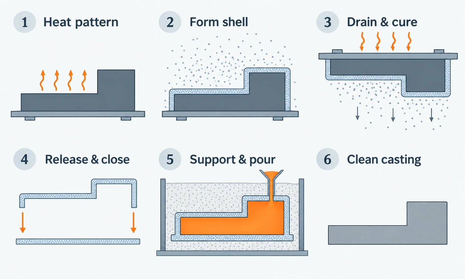
The complete process turns two molded shells and any necessary cores into a supported cavity, then converts that cavity into a finished metal part.
1. Prepare and Heat the Metal Pattern
The pattern is a metal tool that carries the shape needed for a mold half. Its design accounts for metal contraction during cooling, machining allowances, and the draft needed to remove the cured shell. Features for metal entry, feeding, alignment, and ejection may also be incorporated.
The pattern is heated to a controlled temperature, and a suitable release agent helps the shell separate cleanly. Uniform temperature across the tool supports consistent shell formation.
2. Apply the Resin-Coated Sand
In a common arrangement, a box of coated sand is clamped against the pattern and inverted so the sand covers its hot surface. Other equipment applies or blows the sand into contact with the tooling.
The sand must reach the surfaces that will define the shell. Contact time is controlled so the required bonded layer develops without treating the entire sand supply as mold material.
3. Remove Loose Sand and Complete the Cure
The sand that remains loose is tipped away, leaving the initial shell on the pattern. Continued heating on the tool or an additional oven-curing stage develops its rigidity.
The shell must have enough strength for removal, assembly, and pouring. Too little cure can leave it weak; excessive or uneven heating can also impair its properties. Temperature and time therefore belong to a qualified sand, resin, and tooling combination.
4. Release the Shells and Assemble the Mold
Ejectors or another removal mechanism release the cured shell halves from the metal tooling. Their edges and cavity surfaces need to remain intact and undistorted.
Any cores required for internal features are positioned before the halves are closed. The halves are aligned and secured with adhesive, clamps, clips, or another appropriate arrangement. Accurate closing preserves the relationship between the two sides of the casting.
5. Support the Mold and Pour the Metal
The assembled shell may be placed in a container, or flask, with backing material such as sand or steel shot. The support arrangement depends on shell strength, casting size, orientation, and the loads imposed by pouring.
Molten metal flows through the gating system—the channels that deliver it into the cavity. Feeders, where required, supply additional liquid metal as the casting contracts during solidification. A rigid shell does not remove the need to design these filling and feeding paths.
6. Remove the Shell and Finish the Casting
After solidification and sufficient cooling, the disposable sand shell is broken away. Cores are removed from internal spaces, and the gates and feeders are cut off.
Cleaning, heat treatment, machining, surface finishing, and inspection follow according to the alloy and drawing. The metal pattern can produce the next mold, but a new sand shell is needed for the next casting cycle.
Shell Molds, Shell Cores, and Part Geometry
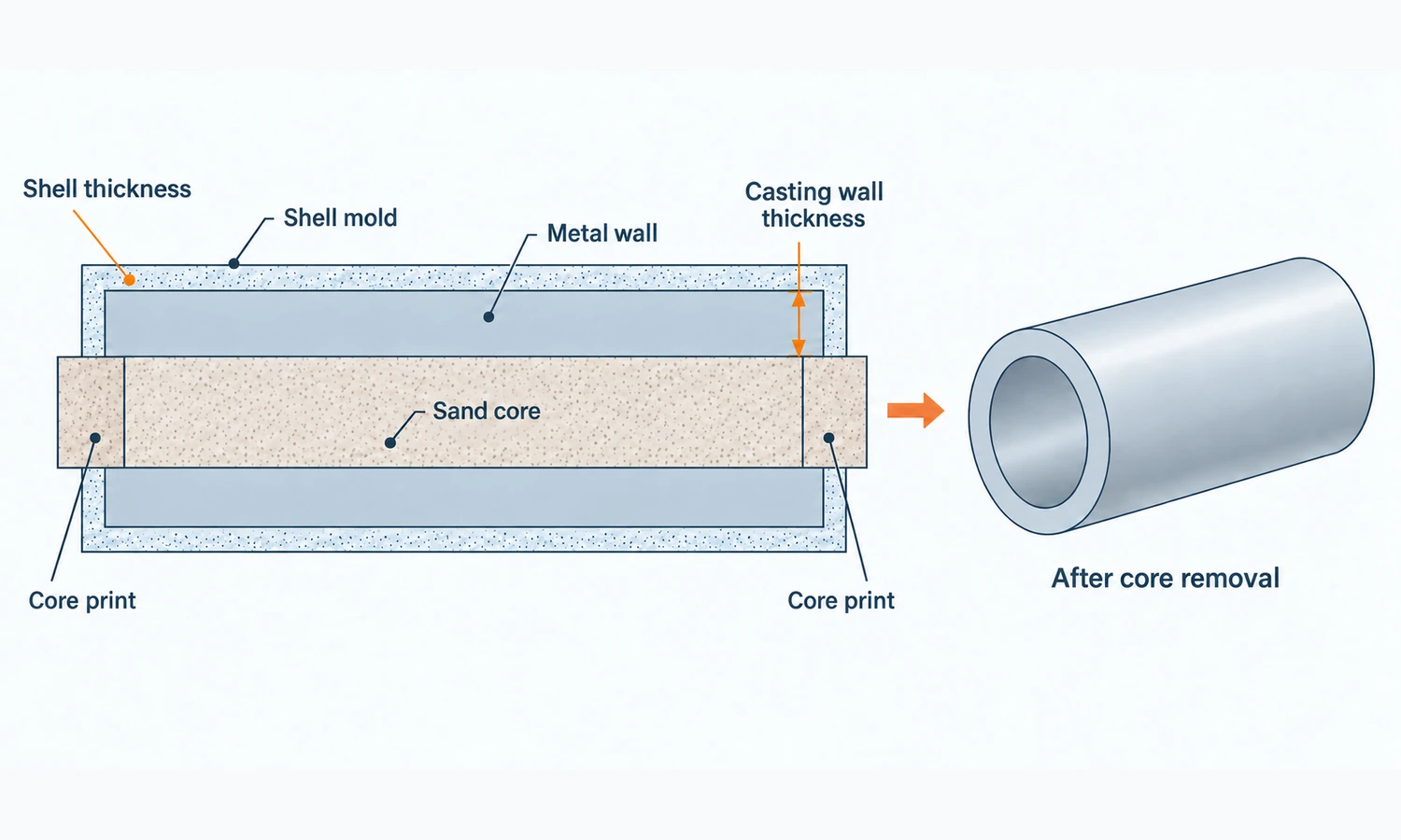
The shell mold forms the casting’s external boundary. A core occupies space inside that boundary to create a hole or passage where metal must not remain. These two elements perform different jobs even when both are made by the shell process.
A shell core is produced from resin-coated sand using a heated metal core box, which is a tool for forming the core’s shape. The same heating and curing principle can produce a hollow shell core. Its hollow construction describes the core itself; the outer surface of that core determines the opening left in the casting.
Consider a pump housing with a curved internal passage and a mounting face. The shell halves establish the outside shape. A core forms the passage, while later machining can establish the mounting face and other precision features.
This example reveals several design requirements. The core must be located and supported so the metal wall around it has the intended thickness. After casting, the core sand must be removable through accessible openings. The passage also needs a practical way to verify its condition and cleanliness.
The external mold has its own access requirements. Each cured half must leave the metal pattern, so draft and a suitable parting arrangement remain necessary. Where the halves meet, a parting line remains on the casting. Tool design and assembly control can reduce mismatch and flash at this joint, but shell molding does not eliminate the joint.
Advantages and Limitations of Shell Molding
Shell molding’s main advantages come from the fine sand, rigid cavity, reusable tooling, and controlled mold-making cycle.
- Smoother as-cast surfaces. Fine grains reproduce the pattern surface closely. This can reduce cleaning and leave more noncritical surfaces suitable for use without machining.
- More consistent dimensions. Metal tooling and a properly cured shell help reproduce the same cavity over repeated cycles. This can make subsequent machining more predictable.
- Good reproduction of detail. The shell forms directly against the pattern, supporting detailed external shapes and, in suitable designs, less draft than conventional green-sand molding.
- Repeatable production. Shell-making cycles can be mechanized or automated. The shell itself also generally uses less mold material than a full green-sand mold, although backing may still be needed.
These advantages are relative to conventional molding conditions, rather than fixed performance values for every part. A smooth pattern, suitable sand, stable heating, and accurate assembly all contribute to the result.
The principal limitations follow from the same process. Metal tooling and heating equipment require investment. Resin-coated sand, curing, and shell handling remain recurring costs. Shells can crack or distort before pouring, and large or awkward geometries may be difficult to support and handle.
Complexity also moves into coremaking and assembly when the part has internal features. A design with several cores may gain a good external surface while retaining substantial work inside the mold. The useful benefit is the work removed from the complete component.
Materials and Applications of Shell Mold Casting
Shell molding is used for both ferrous and nonferrous castings. Industrial applications include cast irons, carbon and alloy steels, stainless steels, aluminum alloys, and copper alloys.
The material still changes the manufacturing requirements. Pouring temperature, metal flow, solidification, and interaction with the sand and binder affect the selected molding system. Experience with one alloy and geometry does not establish the same capability for another.
Housings, pump and valve bodies, connecting rods, and lever arms illustrate the kinds of components for which shell molding may be evaluated. Their reasons for using the process differ:
- A housing may benefit from a consistent external profile while retaining machined mounting faces and bores.
- A pump or valve body brings core location, internal cleaning, and pressure-related acceptance requirements into the decision.
- A connecting rod or lever arm requires the material properties and the geometry of its loaded sections to be considered alongside surface and dimensional requirements.
Shell molding is commonly associated with repeated production of small and medium components, but its industrial range is broader. The ASM Handbook describes castings from a few ounces to about 180 kg. This reported process range provides a sense of scale; shell strength, backing, equipment, alloy, and geometry determine the practical capability for a particular part.
Dimensional Accuracy, Surface Finish, and Machining
Dimensional repeatability means that successive parts stay consistent. Dimensional accuracy means that they meet the intended measurements. A repeatable shell-making cycle can still produce the wrong dimension if, for example, the pattern’s contraction allowance is unsuitable for the casting.
Dimensions develop through several stages: pattern manufacture, thermal behavior during shell making, curing and removal, mold assembly, core location, and metal contraction. A measurement crossing the mold joint depends on the alignment of both halves. A bore formed by a core also depends on where that core sits.
Surface finish has a different set of influences, including the pattern surface, sand grading, resin coverage, release agent, mold-metal interaction, and cleaning. A smoother surface does not automatically have the flatness or positional accuracy needed for assembly.
For the pump-housing example, the outside may be acceptable as cast while a sealing face needs machining. Extra material must be left where machining is planned, and the reference surfaces used to locate the part must allow the required features to be established.
ISO 8062-3:2023 provides a framework for general casting tolerances and machining allowance grades. It does not assign one automatic capability grade to shell molding. The drawing and agreed acceptance requirements determine which features need tighter control and which can use general casting tolerances.
Common Shell Mold Casting Defects
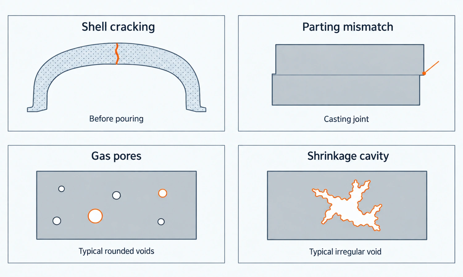
Some defects start in the shell before pouring. Others develop as the metal fills, solidifies, or cools. Separating these stages helps connect a visible problem to the evidence needed to investigate it.
| Problem | What may be happening | Useful checks |
|---|---|---|
| Cracked, soft, or peeling shells | The shell may lack adequate strength or may be damaged during removal, handling, assembly, or heating. | Sand condition, resin distribution, pattern temperature, cure, shell thickness, ejection, and support. |
| Mismatch, flash, or metal leakage | Mold halves may be offset, the joint may open, or a damaged shell may allow metal to escape. | Registration, closing and clamping, core placement, joint condition, shell damage, and backing. |
| Gas pores or pinholes | Gas from the mold or core may be trapped; moisture, entrained air, or melt condition may also contribute. | Gas evolution, permeability, venting, sand and core condition, and melt-quality records. |
| Incomplete filling or cold shuts | Metal may fail to reach a section or advancing streams may fail to join properly. | Filling path, section thickness, heat loss, pouring conditions, and gas escape. |
| Shrinkage cavities or hot tears | Liquid feeding may be inadequate, or contracting metal may be restrained during solidification. | Feeders, hot regions, section transitions, alloy behavior, cooling, and restraint. |
| Sand inclusions or surface penetration | Shell material may break away, or metal may enter the sand structure. | Shell integrity, erosion, local flow, mold-metal interaction, and pouring conditions. |
The table gives starting points rather than one-cause diagnoses. A cracked mold can later leave fins of metal, while an internal pore may appear in a casting whose mold looked sound.
Gas porosity and shrinkage deserve particular care because both leave voids but arise through different mechanisms. Gas control concerns the generation and escape of gas. Shrinkage control concerns supplying liquid metal to a region as it solidifies. Improving one does not necessarily correct the other.
Quality Control from Coated Sand to Finished Part
Process control begins with the materials and mold-making cycle. Relevant checks include sand flow and condition, shell strength, pattern temperature, contact and cure times, shell thickness, assembly, and pouring records.
The AFS Mold & Core Test Handbook includes methods for properties such as permeability, gas evolution, abrasion, and hot deformation. These measurements help test a suspected mechanism and monitor the chosen production system.
Finished-part inspection then addresses the component’s requirements. Visual and dimensional checks assess surfaces and geometry; chemical and mechanical tests address material requirements; radiography, penetrant testing, or other specified examinations address relevant discontinuities. A sound control plan connects these results to the features and acceptance criteria that matter for the part.
Shell Molding vs. Green-Sand, No-Bake, and Investment Casting
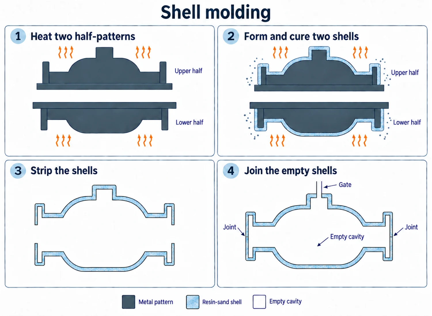
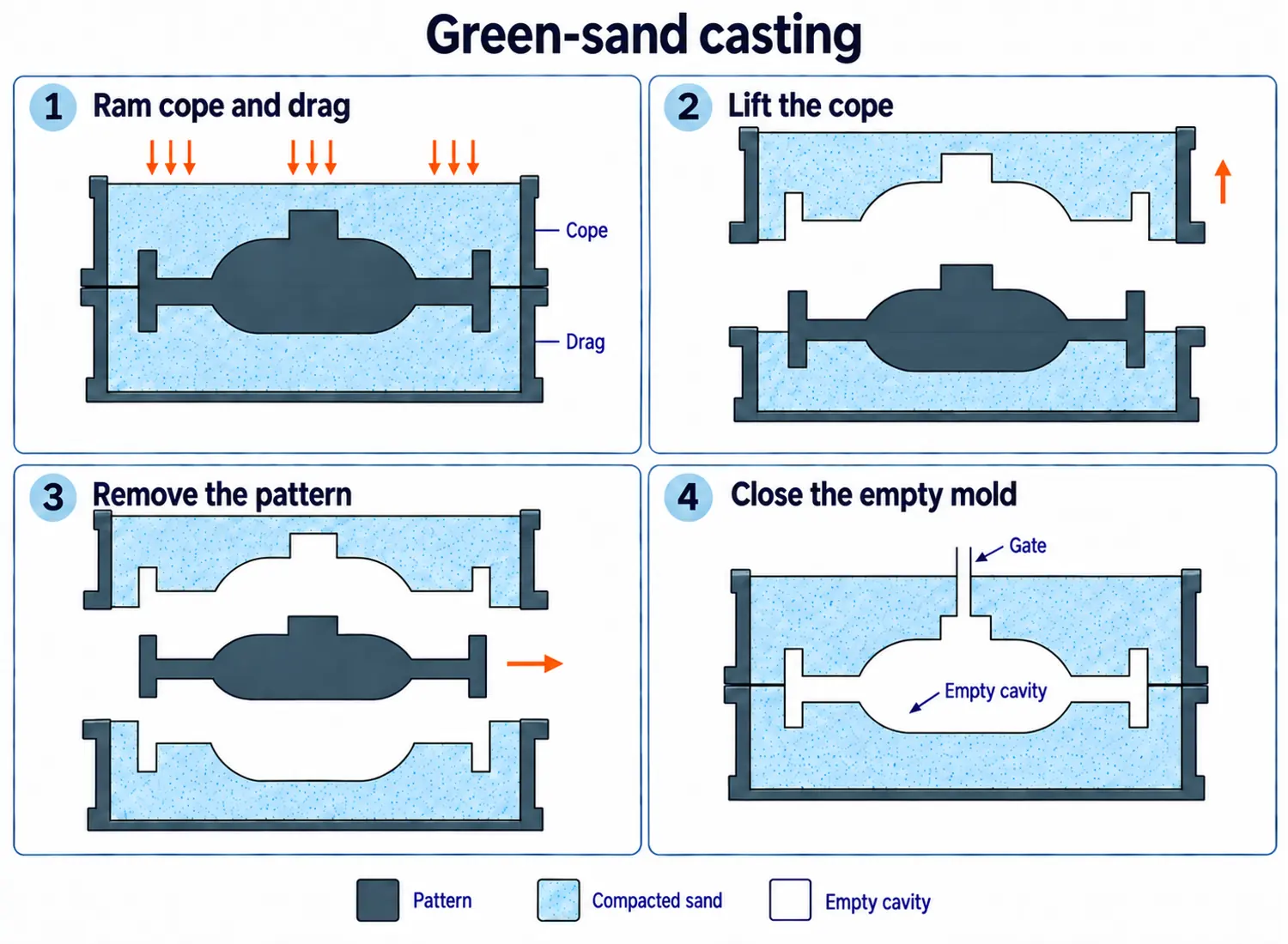
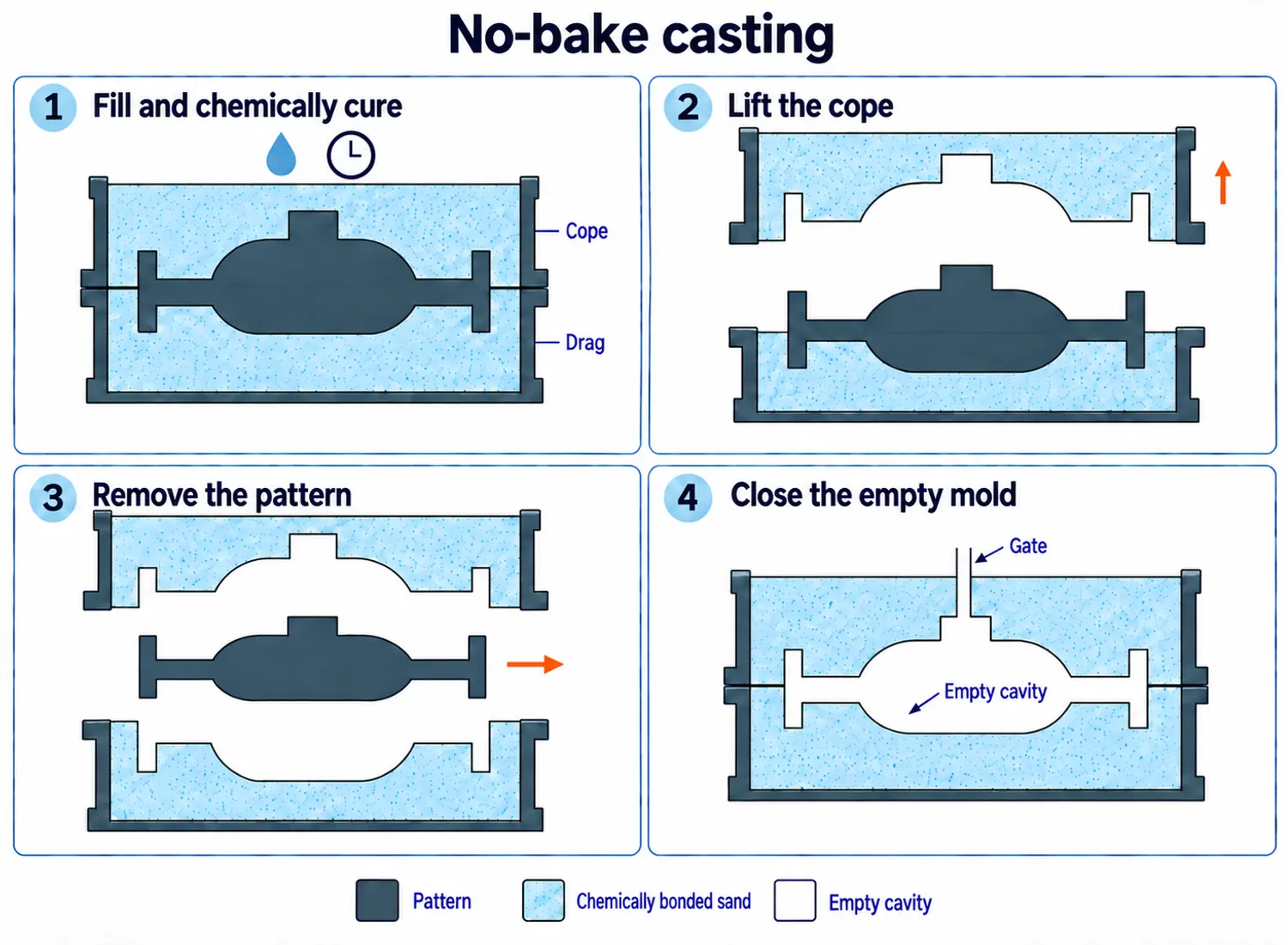
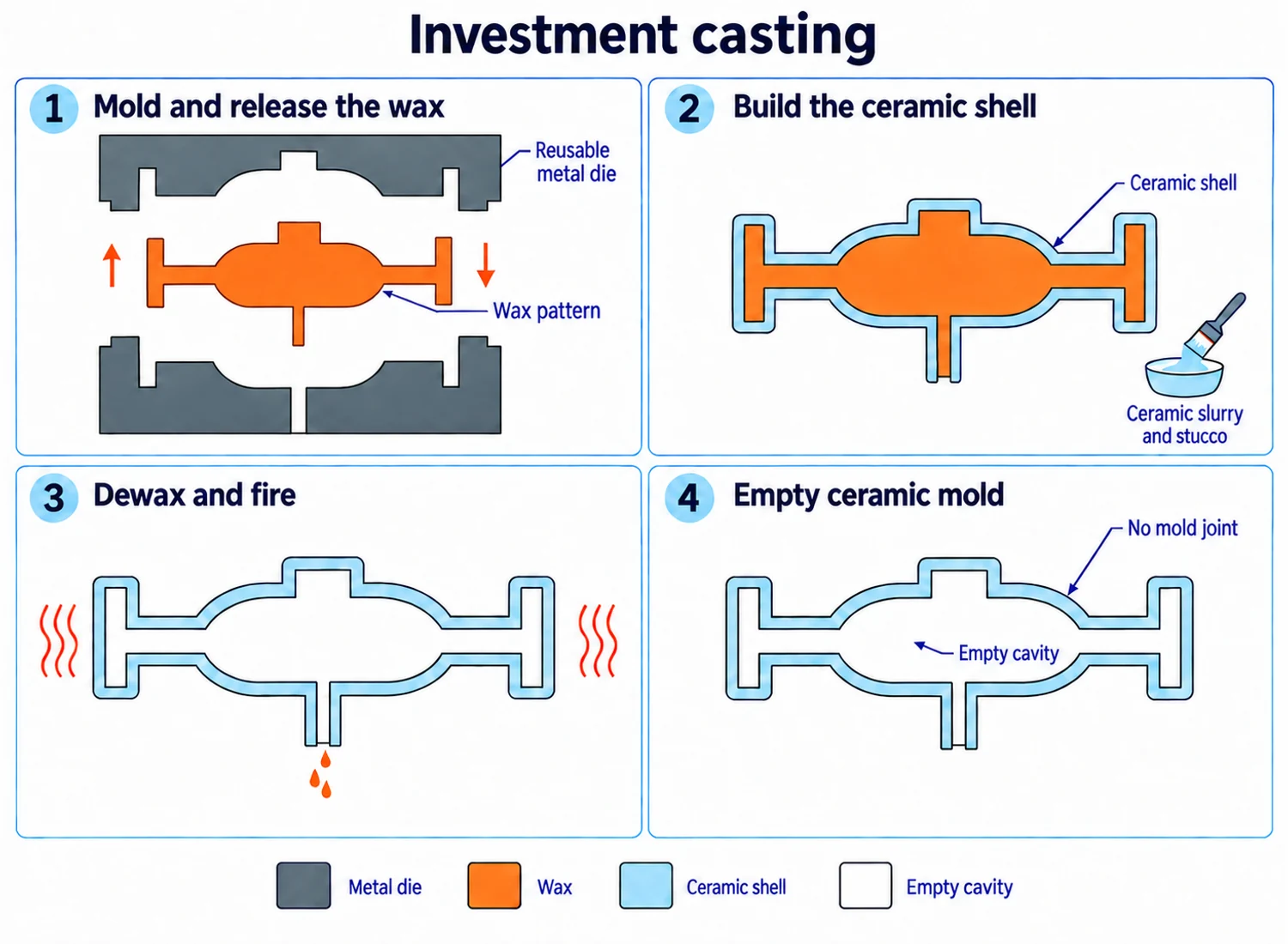
Shell molding is itself a sand casting process. Comparisons with “sand casting” usually refer to a conventional method such as green-sand molding. The distinction begins with how the mold obtains its strength.
| Process | Mold-making method | Main considerations in selection |
|---|---|---|
| Shell molding | Resin-coated sand cures against heated metal tooling to form rigid shell halves. | Repeated geometry, surface and dimensional consistency, tooling investment, shell handling, and quantity. |
| Green-sand casting | Moist, clay-bonded sand is compacted around a pattern and fills the molding flask. | Molding flexibility, sand control, part size, quantity, and the finishing needed to meet the drawing. |
| No-bake casting | A chemical binder hardens sand at room temperature around a pattern. | Often considered for larger molds and lower or moderate quantities, with curing and mold handling included in the comparison. |
| Investment casting | A ceramic shell is built around expendable wax patterns, then dewaxed and fired. | Detail, geometry, alloy, dimensions, surface requirements, wax tooling, shell production, and order quantities. |
The ceramic shell in investment casting is different from the resin-sand shell in shell molding. Investment casting removes a sacrificial wax pattern; shell molding releases each cured sand half from reusable metal tooling.
Each route can change the work required elsewhere. A process with a lower molding cost may need more machining or core assembly. Another may justify more expensive tooling by reducing those operations across a repeat order. The comparison should follow the same part through casting, finishing, and inspection.
Shell Mold Casting Costs and Production Volume
Shell molding has both initial and recurring costs. The metal pattern and process setup must be paid for before production, while coated sand, heating, curing, cores, assembly, and handling continue with every mold.
Repetition spreads the initial investment across more parts. The case becomes stronger when consistent castings also reduce cleaning, machining, or rejected parts. A one-off component or a design subject to frequent changes has less opportunity to recover dedicated tooling costs.
Order quantity alone cannot determine the preferred route. Core complexity, metal utilization in the gating and feeding system, casting acceptance rates, finishing, and inspection also affect the cost of a usable component.
The practical comparison is therefore the total cost of accepted finished parts at the expected batch and lifetime quantities. Shell molding earns its place when its repeatability and finishing benefits outweigh its tooling and mold-production costs for that particular design.
Shell Mold Casting Services from YTD Foundry
YTD Foundry provides shell mold casting alongside investment casting, other sand casting processes, and die casting for custom parts made from drawings or physical samples. Tooling, machining, inspection, surface finishing, and finished-part delivery can be organized around the selected manufacturing route.
For a part review, provide the alloy, drawing or sample, expected quantities, and the critical surfaces, internal features, and acceptance requirements. These details allow the casting process and finishing plan to be considered together, so the proposal addresses the component as it will be used.
FAQs
Does Shell Molding Use a Foam Pattern?
Shell molding uses a reusable metal pattern, which is removed before pouring. In lost foam casting, the expendable foam pattern stays in the sand and decomposes as molten metal enters. The pattern material and the point at which it leaves the process are fundamental differences.
Does a Thin Shell Mold Produce a Thin-Walled Casting?
Not necessarily. Shell thickness describes the sand mold. Casting wall thickness is the space available for metal between mold surfaces or between a mold surface and a core. The mold must withstand handling and pouring, while the metal section must fill and solidify successfully; the two thicknesses serve different purposes.
Can Shell-Molding Sand Be Reused?
Loose sand removed before curing can return to the sand supply, subject to its condition. Sand from a cured and poured shell contains spent binder and may require reclamation before reuse. Resin residues, fines, and changes in sand condition make it a different material stream from the loose return sand.
Does Using Less Mold Sand Make Shell Molding Environmentally Cleaner?
Mold-material consumption is only part of the picture. Resin coating, heating, curing, pouring, and sand recovery involve energy use and potential emissions. The U.S. EPA’s iron and steel foundry emission protocol treats resin-coated sand as a distinct binder system for emissions assessment. Handling and breaking silica-sand molds can also generate respirable crystalline silica dust. Environmental performance therefore depends on the actual materials, energy demand, recovery, and emission controls, rather than shell thickness alone.