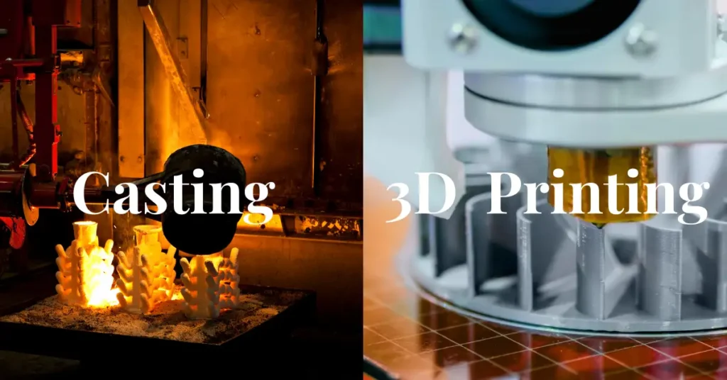
Casting and 3D printing can both turn a digital design into a physical part, but they follow almost opposite manufacturing strategies.
Casting first creates a negative cavity—a mold—and then fills that cavity with liquid material. 3D printing, more formally called additive manufacturing, builds the part directly by adding material layer by layer.
That basic difference influences nearly everything else: equipment, material selection, design freedom, production speed, tooling cost, surface finish, mechanical performance, and the quantity at which each process becomes economical.
The Short Answer
Choose casting when you need:
- Hundreds, thousands, or millions of similar parts
- A low unit cost after production has ramped up
- Large metal components
- A broad selection of established casting alloys
- Consistent production from reusable tooling
- Mechanical properties and certifications already established around conventional foundry processes
Choose 3D printing when you need:
- One part or a relatively small production batch
- Fast design iteration without new tooling
- Complex internal channels, lattices, or organic geometry
- Part-by-part customization
- Assembly consolidation
- On-demand production or replacement parts
This is not an absolute rule. Sand casting can be economical for one-off, very large components, while industrial 3D printing can produce thousands of small parts when several components are nested into one build. The real decision depends on the combination of material, geometry, size, quantity, quality requirements, and production schedule.
What Is Casting?
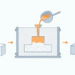
In metalcasting, molten metal is poured or injected into a mold made from materials such as sand, ceramic, or tool steel. The metal fills the cavity, cools, solidifies, and is then removed for finishing.
The American Foundry Society’s overview of metalcasting provides a useful industry definition and notes that common cast metals include iron, steel, aluminum, magnesium, zinc, and copper-based alloys.
“Casting” is actually a family of processes:
- Sand casting uses a usually expendable sand mold. It is flexible, works with many alloys, and can produce very large parts.
- Investment casting surrounds a sacrificial wax or polymer pattern with a ceramic shell. It is well suited to detailed shapes and alloys with high melting temperatures.
- Die casting injects molten metal into a reusable steel die, usually under pressure. Its higher tooling cost is balanced by fast, repeatable high-volume production.
- Permanent-mold casting uses a reusable metal mold but may rely on gravity rather than high-pressure injection.
- Urethane, silicone, plaster, and resin casting use similar mold-and-fill principles at much lower temperatures.
For a broader explanation of these variations, see this guide to different types of casting processes.
What Is 3D Printing?
The ISO/ASTM definition describes additive manufacturing as producing a physical three-dimensional geometry through the successive addition of material. In other words, the machine manufactures the part directly from digital data instead of first making a dedicated mold. The formal terminology is covered by ISO/ASTM 52900.
Like casting, 3D printing is not one process. Major categories include:
- Material extrusion, including FDM or FFF
- Vat photopolymerization, including SLA and DLP
- Powder bed fusion, including polymer SLS and laser-based metal printing
- Material jetting
- Binder jetting
- Directed energy deposition
- Sheet lamination
The NIST guide to additive manufacturing technologies provides concise descriptions of the principal process families.
How the Processes Work
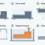
A Typical Casting Workflow
- Create the pattern or die.
A pattern forms the mold cavity in sand or ceramic processes. Die casting instead requires a precisely machined reusable metal tool. - Prepare the mold and cores.
The mold defines the external shape. Removable or sacrificial cores create holes and internal cavities. - Melt and condition the material.
A furnace brings the alloy to a controlled pouring temperature. Chemistry, cleanliness, dissolved gas, and temperature must be managed. - Fill the mold.
Metal enters through a system of sprues, runners, gates, and risers. These features control flow and help compensate for solidification shrinkage. The AFS metalcasting glossary explains these terms in more detail. - Cool and solidify.
Cooling rate and solidification direction influence grain structure, porosity, distortion, and mechanical properties. - Remove and finish the casting.
The mold may be opened, broken, or shaken away. Gates and excess material are removed, followed as needed by blasting, grinding, heat treatment, machining, coating, and inspection.
A Typical 3D-Printing Workflow
- Prepare the digital model.
The CAD model is checked, oriented, and converted into machine instructions. Supports may be added, and multiple parts may be arranged in the same build. - Load and calibrate the machine.
Depending on the process, the feedstock may be filament, liquid resin, polymer powder, metal powder, wire, paste, or bound metal material. - Build the part layer by layer.
A nozzle deposits material, a laser or electron beam fuses powder, or light cures liquid resin. - Cool, cure, or stabilize the build.
Some parts must cool in the powder bed; resin parts require additional UV curing; metal parts may need stress relief before removal from the build plate. - Remove supports and unused material.
This can involve cutting, washing, depowdering, blasting, or machining. - Apply secondary operations.
Common operations include heat treatment, hot isostatic pressing, polishing, sealing, dyeing, coating, CNC machining, and dimensional inspection.
The “print” is therefore only one part of the complete manufacturing cycle.
Equipment: Foundry Line vs. Digital Build Cell
| Production stage | Casting equipment | 3D-printing equipment |
|---|---|---|
| Design preparation | CAD and casting simulation software | CAD, build-preparation, nesting, and slicing software |
| Tool preparation | Patternmaking machines, CNC toolmaking equipment, core boxes or dies | Usually no part-specific hard tooling |
| Material preparation | Melting furnace, crucible, ladle, degassing and temperature-control equipment | Filament dryer, resin system, powder handling station, sieving equipment or wire feeder |
| Part formation | Molding line, die-casting machine, hydraulic clamping system or pouring station | Extrusion printer, resin printer, powder-bed machine, binder-jet system or directed-energy-deposition cell |
| Atmosphere control | Fume extraction and furnace controls | Inert-gas systems and oxygen monitoring for many metal-powder processes |
| Part removal | Shakeout equipment, ejector system, cutoff saws and grinders | Depowdering station, wash unit, support-removal tools, wire EDM or bandsaw |
| Finishing | Shot blasting, heat-treatment furnace, CNC machines and coating equipment | UV-curing unit, heat-treatment furnace, blasting system, HIP equipment and CNC machines |
| Inspection | CMM, X-ray, ultrasonic testing, leak testing and metallography | CMM, optical scanning, X-ray CT, surface metrology and mechanical testing |
A metal 3D-printing installation is not necessarily small or simple. NIST’s Additive Manufacturing Research Center, for example, combines industrial printers with controlled powder handling, heat treatment, EDM, CNC finishing, metallography, and measurement equipment.
Material Options
Casting Materials
Metal casting supports one of the widest material ranges in manufacturing:
- Aluminum alloys
- Magnesium alloys
- Zinc alloys
- Cast iron and ductile iron
- Carbon, low-alloy, and stainless steels
- Copper alloys, including brass and bronze
- Nickel- and cobalt-based superalloys
- Certain titanium alloys
Not every alloy works with every casting method. High melting temperatures may rule out conventional steel dies, while fluidity, oxidation tendency, shrinkage, and hot-tearing behavior can also influence process selection.
Non-metal casting can use:
- Polyurethane
- Silicone
- Epoxy
- Polyester resin
- Plaster
- Concrete
- Glass
- Ceramics
3D-Printing Materials
Polymer 3D printing commonly uses:
- ABS, ASA, PLA, and polycarbonate filaments
- Nylon powders, including PA11 and PA12
- TPU and other flexible materials
- PEKK, PEEK, and PEI for demanding applications
- Photopolymer resins
- Filled or reinforced polymer systems
Metal additive manufacturing commonly uses:
- Stainless and tool steels
- Aluminum alloys
- Titanium alloys
- Nickel-based superalloys
- Cobalt-chrome
- Copper and copper alloys
- Precious metals
The important difference is not simply the number of materials on a list. Casting has a long history of standardized alloys and established property data. Additive manufacturing usually requires a qualified combination of feedstock, machine, build parameters, orientation, and post-processing route.
Changing any one of those variables can change the resulting microstructure and properties.
Production Cycle and Lead Time
Casting and 3D printing measure speed in different ways.
With casting, the longest delay often occurs before the first production part. Patterns, dies, cores, gating systems, simulations, samples, and process validation may all be required. Once the process is established, however, a reusable die can produce parts rapidly.
With 3D printing, production can begin soon after the digital file passes a manufacturability review. There is little or no hard tooling to wait for, but every additional part still consumes machine capacity.
| Project phase | Casting | 3D printing |
| Design change | May require pattern, core, or die modification | Usually requires only a revised digital build file |
| First prototype | Fast with simple sand or printed-pattern casting; slower with production tooling | Often available within days for eligible parts |
| Production ramp-up | Can take weeks or months for complex permanent tooling | Usually limited mainly by validation and available machine capacity |
| Cycle per part | Very fast after automated tooling is running | Each part continues to occupy build volume and build time |
| Scaling strategy | Increase cavities, cycles, or production lines | Add machines, improve nesting, or increase build utilization |
| Best economic range | Highly process-dependent; strongest advantage at medium to high volume | Usually strongest at low volume, customization, and high-complexity production |
As a real-world reference—not a universal promise—Protolabs lists 3D-printing lead times ranging from a few days to around ten days for many standard materials and processes. Its service also advertises one-day production for certain eligible parts.
Production die casting has a much longer front end. Xometry’s die-casting lead-time guidance gives an example of approximately 12–18 weeks to receive initial samples after an order, followed by approval and production. Once the die is approved, however, it can support rapid repetitive manufacturing.
The useful question is therefore not simply, “Which process is faster?” It is:
Do you need the first part quickly, or do you need the ten-thousandth part quickly and inexpensively?
Geometry and Design Freedom
Where Casting Is Strong
Casting is especially effective for:
- Large structural parts
- Thick, substantial metal sections
- Shapes that would waste large amounts of material if machined
- Components requiring established cast alloys
- Repeated housings, brackets, wheels, pump bodies, and engine components
- High-volume thin-walled aluminum, magnesium, or zinc parts produced by die casting
Casting can produce complex geometry, but the designer must consider:
- Parting lines
- Draft angles
- Mold filling
- Solidification shrinkage
- Uniform wall thickness
- Core support and removal
- Tool access
- Ejection from reusable dies
Complex internal passages are possible, but they normally require cores that can be removed, dissolved, collapsed, or left in place.
Where 3D Printing Is Strong
3D printing is especially effective for:
- Internal cooling or fluid channels
- Lattice structures
- Topology-optimized parts
- Patient-specific implants and anatomical models
- Custom fixtures and robotic grippers
- Lightweight aerospace components
- Low-demand replacement parts
- Designs that consolidate several components into one
Additive manufacturing eliminates conventional parting lines and usually does not require draft. However, it introduces a different set of constraints:
- Support structures
- Minimum wall and feature sizes
- Build orientation
- Layer-dependent surface quality
- Thermal distortion
- Trapped powder
- Access for cleaning and inspection
- Machine build-volume limits
A channel that can be printed but not depowdered, inspected, or finished is not necessarily a manufacturable channel.
Surface Finish, Accuracy, and Mechanical Performance
Neither process has one universal accuracy or finish.
A sand casting may have a visibly textured surface, while investment and die casting can reproduce much finer detail. Similarly, an FDM part may show obvious layer lines, while SLA can produce a comparatively smooth cosmetic surface.
Metal powder-bed parts may exhibit attached particles, layer artifacts, and orientation-dependent roughness. NIST discusses these effects in its research on surface roughness in laser powder-bed fusion.
Critical surfaces in both casting and metal 3D printing are frequently CNC machined after the near-net-shape part has been produced. Sealing faces, bearing seats, threads, precision bores, and tight geometric tolerances are common candidates.
Mechanical properties also require careful interpretation:
- Castings may contain gas porosity, oxide inclusions, shrinkage voids, or local microstructural variations.
- Printed parts may contain lack-of-fusion defects, residual stress, porosity, or direction-dependent properties.
- Heat treatment can substantially change either part.
- Metal AM parts may require stress relief or HIP to reduce internal defects.
- Surface condition can affect fatigue performance even when bulk tensile strength is high.
For safety-critical applications, the relevant question is not whether a printed or cast material is “stronger.” The question is whether the complete manufacturing route produces qualified, repeatable properties in the actual part geometry.
NIST’s work on additive-manufacturing part qualification highlights the importance of surface measurement, internal-defect detection, material testing, post-processing, and inspection for critical AM components.
Cost and Production Volume
Casting usually has a high fixed cost and a low variable cost:
- Patterns, dies, core tooling, and process development are paid for upfront.
- The tooling investment is distributed over the production quantity.
- As volume rises, the tooling cost per part falls.
- Automated die casting can achieve very low unit costs.
3D printing usually has a low fixed cost and a higher variable cost:
- Little or no dedicated hard tooling is needed.
- Cost is driven by material, build time, machine occupancy, post-processing, inspection, and yield.
- Producing the second part costs nearly as much as producing the first, although nesting and batch processing can improve the economics.
- Design changes do not normally strand a large tooling investment.
This is why 3D printing is often attractive during product development and early production, while casting becomes more attractive after demand stabilizes.
There is no universal break-even quantity. A small, simple zinc component may justify die casting relatively early. A highly complex aerospace component may remain economical to print throughout its production life because the printed design reduces assembly, weight, inventory, or downstream machining.
Advantages and Limitations
| Casting | 3D printing | |
| Main advantages | Low unit cost at scale; large part capability; broad alloy selection; mature industrial standards; fast production after tooling | No hard tooling; rapid iteration; complex internal geometry; customization; assembly consolidation; digital inventory |
| Main limitations | Tooling cost and lead time; design changes can be expensive; draft, parting, filling, and solidification constraints | Higher unit cost at volume; limited build envelope; slower per-part scaling; supports and post-processing; qualification complexity |
| Typical defects | Shrinkage, gas porosity, inclusions, cold shuts, misruns, flash | Porosity, lack of fusion, warping, residual stress, support marks, trapped powder |
| Sustainability considerations | Tooling and furnace energy can be substantial, but scrap metal and molding sand may be reclaimed | Efficient for lightweight design and on-demand production, but machine energy, support waste, powder handling, and post-processing must be included |
| Supply-chain model | Physical tooling is a key production asset | Qualified digital files and controlled process data become key assets |
Typical Applications
Casting commonly excels in:
- Engine blocks and transmission housings
- Pumps, valves, and impellers
- Construction and mining equipment
- Wheels and automotive structural parts
- Electrical and electronic housings
- Turbine components made by investment casting
- Large industrial machine bases
3D printing commonly excels in:
- Rapid prototypes and functional test parts
- Dental and medical devices
- Patient-specific implants
- Aerospace brackets and ducts
- Complex heat exchangers
- Conformal cooling inserts
- Lightweight robotic components
- Custom jigs, fixtures, and tooling
- Obsolete or low-demand replacement parts
The industrial use of 3D printing is no longer limited to visual prototypes. This overview of 3D printing for production parts discusses the relationship between geometry, material selection, end-use requirements, and production quantity.
Casting and 3D Printing Can Work Together
In practice, the two technologies often complement one another.
A manufacturer can:
- Print a master pattern for sand or investment casting
- Print expendable wax-like patterns directly
- Print sand molds and cores without conventional pattern tooling
- Print prototype molds for resin or silicone casting
- Print conformal-cooled tooling used in another production process
- Print early parts, then transition to casting after the design and demand stabilize
Printed patterns can preserve much of additive manufacturing’s design speed while allowing the final part to use a conventional cast alloy. Xometry provides an example workflow in its guide to 3D-printed molds for casting.
This hybrid route can be particularly valuable during bridge production: printed parts cover early demand while production tooling is being designed and built.
A Practical Selection Checklist
Before choosing a process, answer these questions:
- What material and certified properties are required?
- How many parts are needed now—and over the product’s entire life?
- How soon is the first usable part required?
- Is every part identical, or does each one require customization?
- Does the design contain internal channels, lattices, or inaccessible features?
- How large and heavy is the part?
- Which surfaces require machining or cosmetic finishing?
- What inspection and traceability requirements apply?
- How likely is the design to change?
- Can several components be consolidated into one printed part?
- Can a printed pattern or mold make casting more economical?
- At what production quantity does tooling become less expensive than continued printing?
Final Takeaway
Casting is fundamentally a replication process. It invests time and money in a mold so that the same geometry can be produced efficiently again and again.
3D printing is fundamentally a digital, tool-less production process. It invests machine time in each build but allows geometry to change without rebuilding a physical tool.
If the design is stable, the quantity is high, and conventional cast materials meet the requirement, casting will often deliver the better unit economics. If the quantity is low, the geometry is unusually complex, customization matters, or the design is still evolving, 3D printing will often provide the faster and lower-risk route.
And when neither answer is completely convincing, the best solution may be a combination: use 3D printing to accelerate development or create the mold system, then use casting to scale production.