Casting simulation allows engineers to test how molten metal will fill, cool, and solidify before a mold is committed to production.
Instead of discovering shrinkage, poor filling, trapped air, or feeding problems after tooling has already been made, engineers can first reproduce the process virtually and compare different solutions.
The purpose is not to replace foundry experience or physical validation. It is to move more engineering decisions to the stage where changing a gate, runner, feeder, or process parameter is still relatively easy.
What Is Casting Simulation?
Casting simulation is a computer-based method for modeling what happens to molten metal during a casting process.
A typical simulation starts with the 3D geometry of:
- The component
- Sprues and runners
- Gates
- Risers or feeders
- Overflows or vents where applicable
- Mold or ceramic shell
- Cores and chills where applicable
Engineers then define the material and process conditions.
The software numerically calculates how metal moves through the system, how heat transfers between the metal and mold, how the casting solidifies, and—depending on the software and model—where certain defect risks are likely to develop.
Modern casting packages can model filling and solidification, while more advanced analyses can also examine porosity, thermal stress, hot tearing, distortion, and other process-dependent behavior.
A useful way to think about it is:
CAD describes what the part should look like. Casting simulation asks whether molten metal can actually produce it reliably.
Casting Simulation Is More Than Mold Flow
Casting simulation is sometimes casually called mold flow analysis.
That description is incomplete.
Metal flow is important, but filling is only the first part of the casting problem.
A cavity can fill completely and still produce an unacceptable casting because the metal later solidifies poorly.
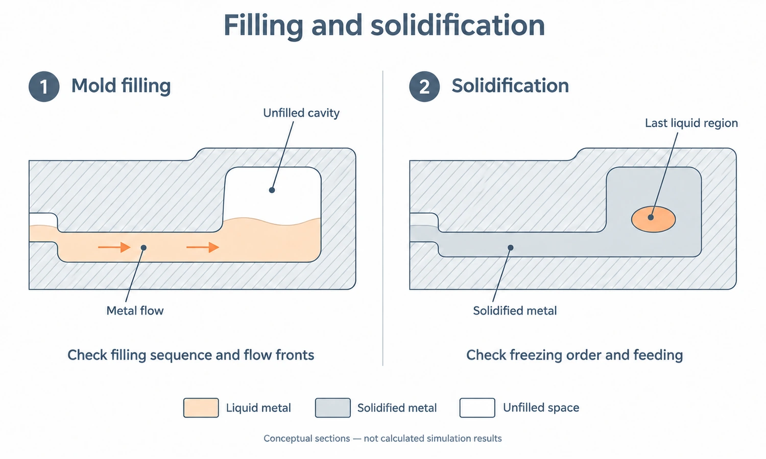
A useful simulation therefore often looks at two major stages separately.
Mold Filling Simulation
Filling analysis shows how molten metal travels from the pouring point through the gating system and into the casting.
Engineers can examine factors such as:
- Filling sequence
- Metal velocity
- Temperature loss
- Turbulent regions
- Air entrapment
- Areas that fill too late
- Potential cold shuts or misruns
- Interaction between different metal fronts
This is particularly useful for checking whether the gate and runner system is delivering metal to the component in a controlled way.
Solidification Simulation
Once the mold has filled, the problem changes.
The question becomes:
Where will the metal freeze first, and where will it freeze last?
Solidification analysis can reveal:
- Hot spots
- Isolated liquid regions
- Feeding paths
- Shrinkage-prone zones
- Cooling-rate differences
- Locations where a feeder may stop working too early
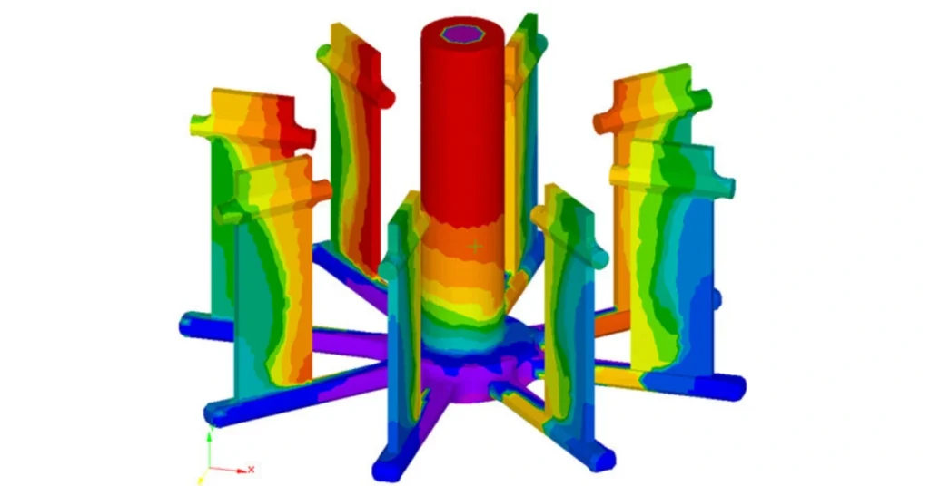
MAGMASOFT, for example, provides investment-casting analyses for mold filling, temperature distribution, liquid fraction, shrinkage porosity, inclusions, cooling, and distortion.
A good casting design has to work during both filling and solidification.
What Information Goes Into a Casting Simulation?
Simulation results depend on the model that goes into the software.
The computer does not know the real foundry conditions unless engineers provide them.
Typical inputs include:
| Input | Why It Matters |
|---|---|
| Casting Geometry | Defines the volume and wall sections the metal must fill |
| Gating / Runner Geometry | Controls how metal enters and distributes through the mold |
| Alloy | Determines thermal and solidification behavior |
| Pouring Temperature | Affects fluidity and available heat during filling |
| Mold / Shell Material | Controls heat transfer away from molten metal |
| Mold Temperature | Influences filling and solidification rate |
| Pouring or Filling Rate | Changes velocity, turbulence, and temperature loss |
| Heat-Transfer Conditions | Affect cooling and solidification |
| Risers / Feeders | Supply liquid metal during shrinkage |
| Chills / Cooling | Locally change the solidification sequence |
A recent ProCAST-based study of stainless steel casting, for example, defined alloy and mold temperature, inlet conditions, gravity, casting-mold heat transfer, and external cooling conditions before comparing different gating and feeding configurations.
This illustrates an important rule:
Simulation quality depends heavily on input quality.
A highly detailed 3D model does not compensate for unrealistic process assumptions.
What Casting Simulation Can Help Predict
Casting simulation is most useful when a possible defect can be connected to fluid flow, heat transfer, solidification, or thermal stress.
Incomplete Filling and Misruns
Thin sections or long flow paths may lose too much heat before the cavity fills.
Simulation can show where metal temperature drops and where flow may stop prematurely.
This allows engineers to investigate changes such as:
- Gate location
- Gate size
- Runner layout
- Pouring temperature
- Filling time
Air Entrapment
When different metal fronts meet or turbulent flow folds over itself, air can become trapped.
Flow simulation helps engineers identify areas where this is more likely to happen.
This information can influence gate positioning, filling direction, venting, or overflow design.
Shrinkage Porosity
Metal contracts as it solidifies.
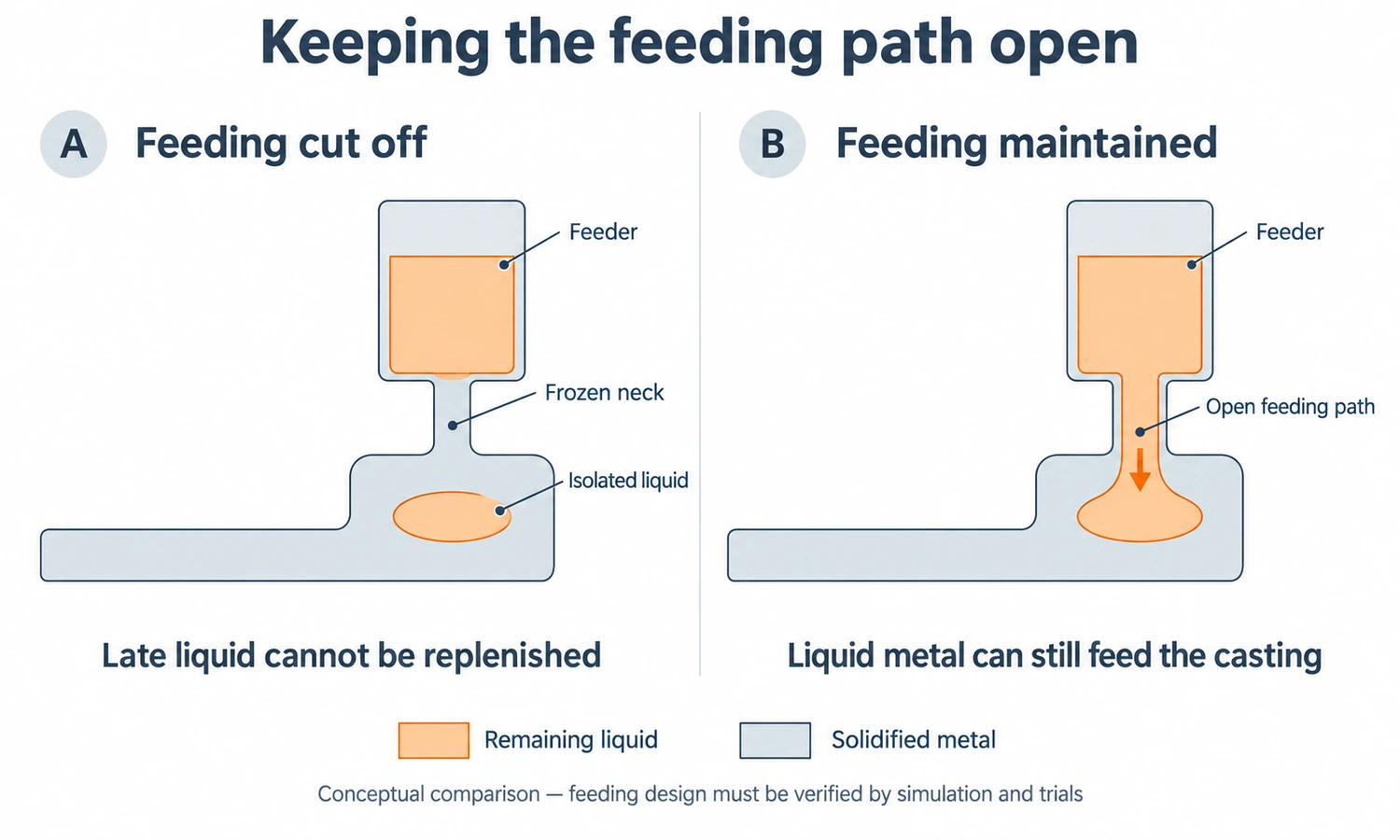
If a region becomes isolated from its source of liquid feed metal before solidification is complete, shrinkage porosity can develop.
Simulation can identify late-solidifying areas and show whether the proposed feeding system can continue supplying them.
Industrial simulation case studies routinely use this relationship between hot spots, feeding and shrinkage to redesign risers, gates and cooling.
Hot Spots
A hot spot is an area that remains hot or liquid substantially longer than surrounding regions.
It often appears where:
- Wall sections become heavy
- Several ribs or bosses meet
- Geometry concentrates metal
- Cooling is restricted
Hot spots are useful indicators because they help engineers understand why shrinkage may appear rather than only seeing its predicted location.
Hot Tearing and Thermal Stress
Some advanced simulation packages model thermal stresses as the casting cools and contracts.
This can help identify locations at risk of:
- Hot tearing
- Cracking
- Residual stress
- Distortion
These predictions are especially valuable when solving one defect could unintentionally create another. For example, improving feeding by keeping an area hot longer can sometimes increase thermal strain elsewhere, so engineers need to consider multiple objectives together.
Casting Defects and What Simulation Looks For
| Casting Problem | What Engineers Look for in Simulation |
|---|---|
| Misrun | Metal freezing before cavity is completely filled |
| Cold Shut | Separate metal fronts meeting under poor temperature or flow conditions |
| Shrinkage Porosity | Isolated late-solidifying regions without sufficient feeding |
| Gas / Air Entrapment | Air trapped by filling pattern or turbulence |
| Inclusion Risk | Flow conditions that can promote oxide or contaminant transport |
| Hot Spots | Areas cooling substantially slower than surrounding sections |
| Hot Tearing | Thermal strain during vulnerable solidification stages |
| Distortion | Uneven thermal contraction and residual stress |
Simulation does not mean the software literally sees every future defect in exactly the form it will appear.
Rather, it shows physical conditions associated with defect formation and helps engineers compare whether one design is more robust than another.
How Engineers Use Simulation to Improve a Casting
The most valuable simulation is not a final report showing that a design has a problem.
It is an engineering loop.
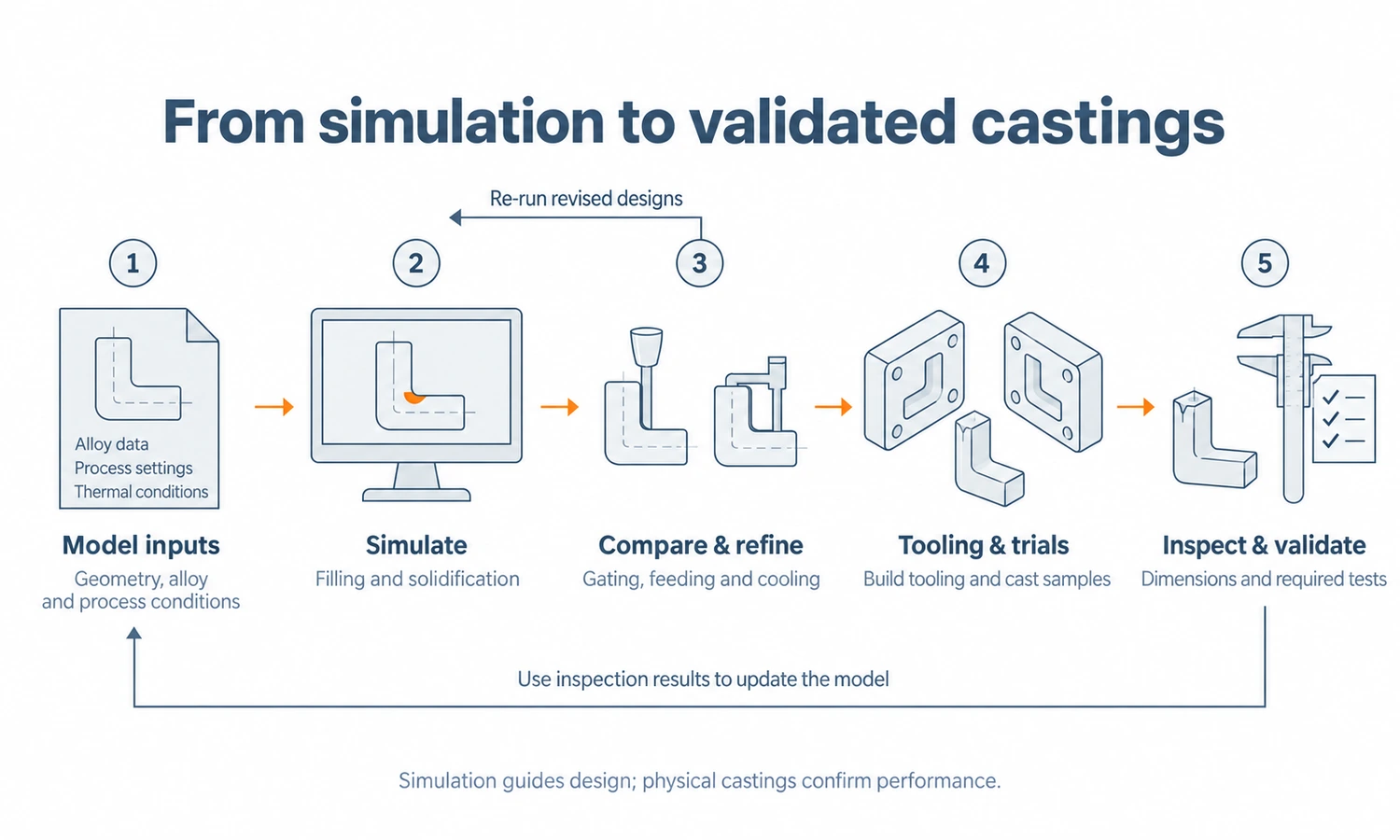
1. Start With the Proposed Part and Casting Layout
The engineer creates an initial casting system based on:
- Part geometry
- Alloy
- Casting method
- Foundry experience
- Required quality level
This first model becomes the baseline.
2. Simulate the Filling Process
The first question is whether metal reaches every region in a controlled way.
If the result shows excessive velocity, poor filling sequence, temperature loss, or trapped air, the gating system can be changed.
3. Simulate Solidification and Feeding
Next, engineers look at how the casting freezes.
If an isolated hot spot cannot be fed properly, possible changes include:
- Moving a gate
- Changing gate size
- Adding or modifying a feeder
- Changing tree orientation
- Adding local cooling
- Modifying component geometry
4. Compare Alternative Designs
The revised design is simulated again.
This is where simulation becomes much more useful than a single colorful result image.
Several variants can be compared before any physical mold is modified.
5. Freeze the Tooling and Process Design
Once the predicted filling and solidification behavior is acceptable, engineers can move forward with greater confidence.
The approved casting layout then informs tooling and production preparation.
6. Validate With Real Castings
Simulation does not eliminate physical validation.
Initial castings still need to be checked through appropriate methods such as:
- Visual inspection
- Dimensional measurement
- Dye penetrant inspection
- X-ray or CT where required
- Sectioning or metallographic evaluation
- Pressure or leak testing
- Mechanical testing
The important difference is that the foundry enters this stage with a process that has already been virtually examined.
Why Run Casting Simulation Before Tooling Is Finished?
Changing a digital model is generally easier than changing physical tooling.
Suppose a first production trial reveals shrinkage beside a critical machined bore.
At that stage, possible corrective actions might require:
- Welding and re-machining tooling
- Changing a runner system
- Adding feeding features
- Rebuilding pattern equipment
- Producing another sample batch
- Repeating inspection
The cost is not only the tooling modification.
It also includes another round of:
- Engineering
- Foundry setup
- Metal
- Labor
- Lead time
- Inspection
Simulation moves some of that learning earlier.
MAGMASOFT describes casting simulation as a way to assess feasibility and compare casting layouts before costly physical trials; industrial examples also show simulation being used before final tool manufacture to evaluate gating and feeding changes.
That does not mean tooling will never need adjustment.
It means fewer obvious casting-system problems need to be discovered by cutting metal first.
Casting Simulation in Investment Casting
Simulation has some special considerations in investment casting.
The mold is not a large block of sand or a reusable metal die.
It is a relatively thin ceramic shell surrounding a tree of components and runners.
That changes the thermal problem.
Investment-casting simulation may need to consider:
- Ceramic shell thickness
- Shell preheat temperature
- Heat loss before pouring
- Radiation between nearby casting surfaces
- Heat accumulation between closely spaced parts
- Casting orientation on the tree
- Gate and runner placement
- Solidification between several parts on one cluster
MAGMASOFT’s investment-casting models, for example, specifically account for ceramic-shell temperatures, thermal radiation, shell cooling before casting, local shell thickness, solidification and shrinkage.
This is important because tree design is not just a way to attach more parts to one sprue.
The way castings are positioned can change both metal flow and heat transfer.
For the physical production steps surrounding this analysis, see YTD’s investment casting process guide.
Casting Simulation in Sand and Die Casting
The physics being solved are related, but different casting processes put emphasis on different problems.
Sand Casting
Sand-casting simulation often focuses heavily on:
- Gating
- Risers
- Chills
- Mold filling
- Solidification
- Shrinkage
- Yield
Because feeders can contain a significant amount of additional metal, simulation can also help engineers balance casting soundness against material yield.
Die Casting
High-pressure die casting introduces a different set of priorities.
Metal enters the cavity very rapidly, so engineers may focus more closely on:
- Filling velocity
- Turbulence
- Air entrapment
- Vent locations
- Overflows
- Die temperature
- Local cooling
- Porosity
The simulation principle is the same:
Model the actual process conditions, then use the results to change the process before production problems become expensive.
What Casting Simulation Cannot Guarantee
Casting simulation is powerful, but it should not be treated as a digital certificate that a casting will be defect-free.
A Simulation Is Only as Good as Its Inputs
If the real pouring temperature is very different from the modeled value, the real casting may behave differently.
The same applies to:
- Material properties
- Mold temperature
- Heat-transfer coefficients
- Filling time
- Process stability
Every Defect Is Not Purely Thermal or Fluid-Flow Driven
Some defects can also result from:
- Dirty metal
- Damaged ceramic shell
- Poor wax quality
- Operator error
- Contamination
- Incorrect heat treatment
- Tool wear
- Actual process variation
A filling and solidification model cannot automatically predict every one of these.
Models Simplify Reality
Numerical simulation divides a physical process into mathematical elements or control volumes.
Mesh size, solver assumptions, material databases, boundary conditions, and selected defect criteria all affect the result.
Different software packages can also use different models.
Engineering Interpretation Still Matters
Seeing a red region on a simulation plot is not enough.
An engineer still needs to ask:
- What physical condition does this result represent?
- Is it relevant to the customer’s acceptance criteria?
- What change can reduce the risk?
- Will that change create a different problem?
Simulation supports engineering judgment.
It does not replace it.
How Accurate Is Casting Simulation?
There is no useful universal percentage for casting-simulation accuracy.
Accuracy depends on:
- The physical model
- Material data
- Boundary conditions
- Mesh resolution
- Process stability
- Calibration
- The type of defect being predicted
The more useful question is:
Has the simulation method been correlated with actual castings produced by that process?
Published foundry studies commonly validate simulation against physical castings, X-ray/CT results, sectioning or measured defect locations. A recent stainless-steel casting study, for example, used the same defined boundary conditions to compare alternative gating and feeding systems and then related the simulation to casting performance.
Simulation is therefore strongest as a comparative engineering tool:
Design A shows an isolated hot spot and Design B maintains a better feeding path.
That comparison can be extremely useful even when the software cannot promise an exact defect size down to the millimeter.
Common Casting Simulation Software
Several commercial platforms are used in the foundry industry.
Examples include:
- MAGMASOFT
- ProCAST / QuikCAST
- FLOW-3D CAST
- NovaFlow&Solid
- SOLIDCast / FLOWCast
- Other process-specific CAE systems
They differ in:
- Numerical method
- Supported casting processes
- Material databases
- Optimization tools
- Stress and microstructure modeling
- User workflow
- Computing requirements
For example, ProCAST includes filling, solidification, porosity and stress/distortion analysis, while FLOW-3D CAST focuses heavily on fluid-flow and solidification simulation for foundry processes.
For a casting buyer, however, the software brand is usually less important than how the foundry uses it.
Owning simulation software does not automatically mean the process is optimized.
What Should a Buyer Ask About Casting Simulation?
If a foundry says it uses casting simulation, useful questions include:
What Is Being Simulated?
Is the foundry only checking solidification?
Or is it also evaluating:
- Filling
- Gating
- Feeding
- Air entrapment
- Stress
- Distortion
The answer should match the risks in your part.
Is Simulation Done Before Tooling Is Finalized?
This is one of the most important questions.
Simulation delivers greater value when its results can still influence:
- Gate location
- Runner design
- Feeder design
- Casting orientation
- Local geometry
Running a simulation only after tooling is complete greatly reduces the range of inexpensive corrections available.
Are Alternative Designs Compared?
One simulation tells you how one proposed process behaves.
Several simulations can tell you which process design behaves better.
How Are Results Validated?
Ask what happens after the first castings are produced.
Do inspection results feed back into the simulation and process design?
That closed loop is much more valuable than simulation existing as an isolated engineering document.
How YTD Uses Casting Simulation Before Tooling and Production
At YTD Foundry, casting simulation is part of the engineering work carried out during mold and process development.
Before committing a new investment-casting project to production tooling, the casting design can be evaluated together with the proposed gating and feeding system.
The purpose is to identify potential problems while changes are still relatively easy to make.
Depending on the project, the engineering review can examine factors such as:
- Metal filling
- Filling sequence
- Temperature distribution
- Solidification behavior
- Hot spots
- Shrinkage risk
- Gating and feeding arrangement
If the simulation indicates a problem, the casting layout or process design can be adjusted and evaluated again before tooling and production are finalized.
This work fits into YTD’s broader mold design and manufacturing workflow, where tooling is developed together with castability, shrinkage, pattern design and production requirements.
After the mold is manufactured, trial wax patterns and first castings are still inspected and validated.
In other words:
Simulation reduces avoidable trial-and-error before tooling. Physical samples confirm that the real process matches the engineering intent.
For customers, this matters more than receiving a simulation screenshot.
The real value is having tooling, casting design, simulation, trial production and inspection connected within the same development process.
Final Thoughts
Casting simulation is most valuable before the foundry commits to tooling and production.
It allows engineers to test filling, solidification, gating and feeding decisions virtually, compare alternatives, and address likely defect mechanisms earlier.
At YTD, simulation is used as part of mold and casting-process development, followed by real sample production and inspection. The objective is not to replace physical validation, but to begin it with a better-engineered casting process.
FAQs
What Is Casting Simulation Used For?
Casting simulation is used to model metal filling, heat transfer and solidification before production. It can help engineers evaluate gating, feeding, temperature distribution and risks such as shrinkage, incomplete filling, trapped air, hot spots and distortion.
Can Casting Simulation Predict Porosity?
It can predict conditions associated with several types of porosity, especially shrinkage porosity and, in suitable models, gas or air-entrapment risk. The accuracy depends on the process model and input data, and simulation results should still be validated against real castings.
Is Casting Simulation the Same as Mold Flow Analysis?
Not exactly. Mold filling or flow analysis is one part of casting simulation. A complete casting study may also include solidification, feeding, porosity, stress, distortion and other process-specific analyses.
Is Casting Simulation Done Before or After Mold Design?
Ideally, it is integrated into process and tooling design before the tooling is finalized. This allows engineers to modify gating, feeding, orientation or other design features while changes are still relatively inexpensive.
Does Casting Simulation Eliminate Trial Castings?
No. It reduces unnecessary trial-and-error and helps start physical validation from a better process design, but first-article casting, inspection and process validation are still necessary.
What Files Are Needed for Casting Simulation?
The foundry normally needs a 3D model of the component together with material and process requirements. The engineer then creates the gating, runner, feeder, mold or shell geometry and defines process conditions such as alloy, pouring temperature and mold conditions.