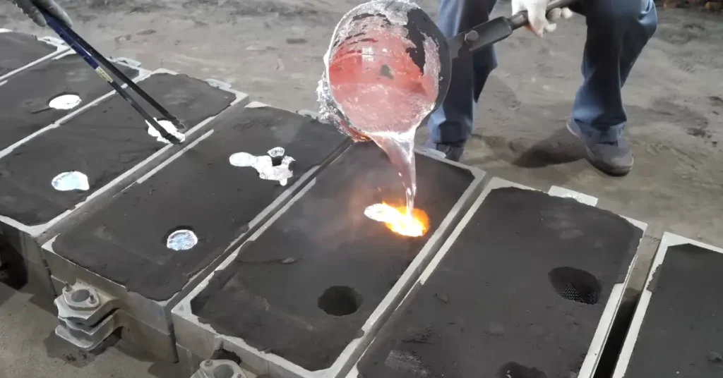
Aluminum sand casting commonly pours molten aluminum alloy into a cavity formed in bonded sand. After the metal solidifies, the sand mold is broken apart to release the casting. A reusable pattern can make the external shape, while separate sand cores can create holes, chambers, and internal flow passages.
The process can produce anything from a simple bracket to a large housing with internal features, but “sand cast aluminum” does not describe one fixed capability. The alloy, sand binder, pattern, cores, filling and feeding system, heat treatment, machining, and inspection all change the result. Understanding those relationships is more useful than looking for one universal pouring temperature, shrinkage allowance, wall thickness, or tolerance.
Aluminum Sand Casting: Definition, Typical Parts, and Process Fit
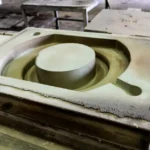
Sand casting is an expendable-mold process. In the bonded-sand routes discussed here, sand grains need a binder so they can be compacted or cured into a stable mold. A pattern leaves the main cavity, and the foundry adds channels that guide molten metal into the part and feed it while it solidifies. Once the casting is cool enough to handle, the mold is destroyed during shakeout.
Aluminum is attractive for many cast components because it combines relatively low density with a wide range of alloy and heat-treatment options. Pump housings, valve bodies, manifolds, gearbox housings, engine components, brackets, and enclosures are common examples of shapes that may suit aluminum sand casting. The application name alone does not establish the right alloy or process; pressure, load, corrosion, temperature, wall sections, and inspection requirements still have to be defined.
The Aluminum Association describes sand casting as a versatile aluminum-forming route that is generally slower than die or permanent-mold casting but often considered for smaller quantities, complex designs, and very large castings. These are broad tendencies. Tooling, mold labor, core complexity, finishing, and the supplier’s equipment determine the actual fit for a part.
The Aluminum Sand Casting Process, Step by Step
The production sequence is easy to summarize, but each stage contains decisions that affect the finished component.
1. Pattern and Core Tooling
The pattern represents the external form that will be left in the sand. It may be made from wood, resin, metal, or another suitable material, depending on part size, expected quantity, molding method, accuracy, and how often the tooling must be handled.
A pattern is not always a one-to-one copy of the finished component. The tooling may include draft so it can be withdrawn without tearing the mold, dimensional allowance for alloy contraction, extra stock on machined surfaces, core prints that locate internal cores, and compensation for predictable distortion. Those allowances are developed for the actual alloy, geometry, and production route rather than copied from one general percentage.
2. Sand Mold and Core Formation
Prepared sand is compacted or cured around the pattern. In a conventional horizontal mold, the upper half is the cope and the lower half is the drag. Removing the pattern leaves the cavity, and the two halves are aligned and closed around any required cores.
Cores occupy the spaces that must remain hollow. They can create ports, water jackets, pump passages, and enclosed chambers that a pattern alone cannot form. A core must be strong enough to survive handling and metal pressure, remain correctly positioned, allow gases to escape, and break down or clean out after pouring. A complicated core package may be possible, but it adds tooling, molding, dimensional, cleaning, and inspection work.
3. Gates, Risers, Vents, and Chills
The sprue, runners, and gates carry aluminum into the cavity. Their layout affects flow speed, turbulence, oxide formation, temperature loss, and whether distant or thin areas fill before the metal freezes. Filters may be included where the process design calls for them.
Risers or feeders hold additional liquid metal that can compensate for contraction as the casting solidifies. Vents provide paths for air and evolved gases. Chills can accelerate cooling in selected areas and change the solidification sequence. The size and location of each feature follow the casting geometry, alloy, section thickness, and filling and feeding analysis; they are not generic accessories placed by a fixed formula.
4. Aluminum Melting, Pouring, and Solidification
The foundry prepares a controlled aluminum alloy charge, melts it, checks or adjusts chemistry as required, and manages melt cleanliness and dissolved gas before pouring. Molten metal then enters the assembled mold and fills the cavity around the cores.
Aluminum’s melting point is not a universal pouring temperature. A usable window depends on the alloy’s liquidus and solidus range, the length and thickness of the flow path, the sand system, melt treatment, mold condition, transfer time, and equipment. Raising temperature may improve flow in one situation while increasing oxidation, gas pickup, mold reaction, or solidification problems in another.
5. Shakeout, Finishing, and Inspection
After sufficient cooling, shakeout separates the casting from the sand. Gates and risers are removed, residual sand is cleaned away, and the surface is finished as needed. Heat treatment, straightening, machining, coating, and inspection are added only when the alloy, drawing, purchase specification, or final use requires them.
The pattern can make another mold, and suitable sand may be conditioned for further use. The poured mold itself is not reusable. Our broader sand casting guide explains how patterns, cores, molds, and finishing fit into the general process.
Sand Molding Systems for Aluminum Castings
Sand casting is often mistaken for green sand casting, but green sand is only one binder system. Aluminum can be poured into several kinds of bonded-sand molds, and the choice changes mold preparation, strength, handling, gas behavior, reclamation, surface reproduction, and cost.
| Molding route | How the sand holds its shape | Why it may be considered |
|---|---|---|
| Green sand | Clay and controlled moisture bond the sand in its undried state. | Short molding cycles, sand recirculation, and compatibility with manual or automated production. |
| No-bake or air-set | A chemical binder cures at room temperature. | Rigid molds and cores for production arrangements where cure time, handling strength, size, or geometry suit the project. |
| Shell molding | Resin-coated sand cures against a heated metal pattern. | A thin, rigid shell and a different balance of tooling, surface reproduction, dimensional control, and production quantity. |
| 3D-printed sand | A printer selectively deposits binder to build a mold or core directly from digital geometry. | Complex cores, prototypes, design changes, or quantities that may not justify conventional pattern and core tooling. |
The binder name does not predict the finished casting by itself. Grain distribution, binder condition, compaction or cure, mold coating, core design, pouring, and process control still interact. Our guide to sand casting materials explains why base sand, binder, additives, coatings, and cores must be evaluated as a system.
Aluminum Alloys Used for Sand Casting
Industrial aluminum sand castings use casting alloys selected for their behavior during filling and solidification as well as their final properties. Designations such as 356.0, A356.0, A357.0, and 319.0 are examples encountered in aluminum casting, but they are not interchangeable and none is the best choice for every application.
Silicon, copper, magnesium, and other alloying elements change fluidity, solidification behavior, heat-treatment response, strength, corrosion resistance, machinability, and weldability. The required temper adds another layer: the same alloy in an as-cast condition and after an appropriate solution-and-aging treatment will not have the same properties.
ASTM B26/B26M-25 covers registered aluminum-alloy sand castings for general applications and addresses alloy and temper designation, chemical composition, heat treatment, and mechanical-property requirements. It also makes clear that highly stressed or safety-critical components may need additional mechanical-property, integrity, and verification requirements. Writing “ASTM B26” on a page does not define every acceptance condition for a part.
Can 6061 Aluminum Be Sand Cast?
6061 is a wrought-alloy designation widely associated with extruded, rolled, and machined products. It should not be treated as the default sand-casting grade simply because an existing machined component is made from 6061.
If a design is being converted from wrought 6061 to a casting, the material decision should return to the required strength, corrosion behavior, temperature, weldability, machinability, and inspection conditions. A registered casting alloy and temper can then be selected and validated for the new manufacturing route. Matching a familiar alloy number is less important than meeting the finished part’s specification.
Design Guidelines for Aluminum Sand Castings
A casting-friendly design gives the pattern a clean withdrawal path, lets metal fill before freezing, allows solidification contraction to be fed, supports cores, and leaves practical access for cleaning and machining.
Wall Thickness and Section Changes
Uniform sections are easier to fill and cool predictably than abrupt changes from thin walls to heavy masses. Thick intersections, oversized bosses, and clustered ribs can create hot spots that remain liquid after surrounding metal has begun to solidify. If the feeding path closes too early, shrinkage may form in or near that region.
Gradual transitions and useful fillets can improve metal flow, reduce sharp stress concentrations, and make the thermal change less severe. This does not create one universal minimum wall or fillet radius. Flow length, alloy, mold condition, orientation, and the selected sand process change what can be produced.
Draft and Parting-Line Design
Draft helps the pattern leave the sand without dragging or breaking the cavity surface. The required angle depends on surface depth, pattern material, molding method, orientation, and the condition of the sand. Features that cross the parting line also introduce alignment and flash considerations.
An undercut may require a loose pattern piece, a core, a different parting arrangement, or a redesign. Calling sand casting “geometrically flexible” does not mean that every feature can be molded without draft, joints, or extra tooling.
Machining Allowance and Functional Surfaces
Bores, sealing faces, bearing seats, threaded holes, and locating datums often need machining because their fit, form, or position is more demanding than the surrounding cast surface. Tooling must leave enough stock for cleanup while preserving a stable way to locate the casting during machining.
Marking the final machining datums early helps the foundry place parting lines, gates, risers, and cores without creating avoidable access or tolerance problems. A smoother-looking casting does not establish whether two functional surfaces are flat, concentric, or correctly positioned.
Porosity Causes in Aluminum Sand Castings
Porosity is not one defect with one cause. Gas pores, solidification shrinkage, entrained air, and oxide-related cavities can overlap in appearance, especially after machining exposes a subsurface indication.
Hydrogen Gas Porosity
Hydrogen is more soluble in liquid aluminum than in solid aluminum. As the casting freezes, dissolved hydrogen can come out of solution and form pores if it cannot escape. Charge condition, moisture, furnace atmosphere, melt handling, holding time, and treatment practice can influence hydrogen pickup and removal.
Rounded pores may suggest a gas mechanism, but appearance alone is not proof. Their size, distribution, location, relation to the cast surface, and connection with other indications should be compared with melt records and the solidification pattern.
Shrinkage Porosity
Aluminum contracts as it solidifies. If a region remains hot after its liquid feeding path has closed, it may not receive enough metal to compensate, leaving an irregular shrinkage cavity or distributed microshrinkage. Section changes, riser performance, gating, chills, alloy freezing range, and thermal gradients all influence this mechanism.
Adding a larger riser is not automatically the answer. The foundry first needs to establish which region freezes last and whether liquid metal can reach it at the required time. A change that feeds one hot spot can also alter yield, cooling, and another section of the part.
Oxide Films and Sand Inclusions
Liquid aluminum rapidly forms an oxide film. Turbulent transfer or filling can fold surface films into the metal, while dross, refractory fragments, or other material can also become trapped. Sand inclusions arise when grains or pieces of the mold or core enter the cavity.
Melt cleanliness, transfer practice, gating, filters, mold strength, core integrity, and pouring consistency all deserve review. A visible cavity after machining might involve gas, shrinkage, or a folded oxide film; naming it correctly requires more than one photograph. Our sand casting defects guide shows how location, morphology, records, and inspection evidence narrow the diagnosis.
Tolerance and Surface Finish in Aluminum Sand Casting
No single tolerance or roughness value applies to every aluminum sand casting. Green sand, no-bake, shell molding, and printed sand do not reproduce the mold surface in the same way. Part size, feature length, core location, parting alignment, pattern condition, mold hardness, alloy contraction, heat treatment, and machining all change dimensional results.
The Aluminum Association separates its sand- and permanent-mold standards into engineering and metallurgical series. That division is useful: dimensional accuracy, machining allowance, and surface condition are not the same question as alloy, temper, and mechanical properties. ISO 8062-3:2023 likewise provides a framework for general casting tolerances and machining allowance grades rather than one guaranteed number for the entire process.
A drawing should identify critical dimensions, datums, geometric controls, machined surfaces, and any area where the as-cast texture matters. The foundry can then state which features remain as cast and which need machining, and validate the proposed route through tooling review and samples.
Heat Treatment for Aluminum Sand Castings
Heat treatment is used when the selected alloy and required temper call for it. Solution treatment, quenching, and artificial aging can change strength and other properties in heat-treatable casting alloys, but the schedule belongs to the alloy, section size, specification, and equipment.
Terms such as T6 and T7 do not describe one identical cycle for every casting. Quenching can also introduce distortion or residual stress, especially in shapes with uneven sections. ASTM B917/B917M-25 addresses heat treatment of aluminum-alloy castings and includes furnace temperature, measurement, and process-control requirements. It applies when the material specification, drawing, or order requires the relevant treatment.
Inspection Methods and Acceptance Criteria
Inspection begins with what the part must do. Visual examination can assess surface condition, dimensional inspection can verify size and geometry, and chemical analysis can confirm alloy composition. Hardness and mechanical tests answer property questions. Leak or pressure tests evaluate containment under defined conditions.
Liquid penetrant testing can reveal surface-breaking indications in suitable nonporous areas. Radiography is useful for many volumetric internal discontinuities, although coverage, thickness, orientation, image quality, and the expected defect all affect sensitivity. Digital radiography and computed tomography use different equipment and reference arrangements from conventional film.
ASTM E155-20(2026) supplies reference radiographs for classifying selected discontinuities in aluminum and magnesium castings within stated conditions. It does not automatically assign an acceptable severity to a component. The drawing, purchase order, applicable product standard, and agreed quality zones must define the method, coverage, reference level, sampling, and acceptance criteria.
Aluminum Sand Casting Compared with Other Processes
The alternatives become easier to compare when every route is measured against the same finished part.
| Process | Often considered when | Questions to compare |
|---|---|---|
| Sand casting | Quantity, size, complex geometry, internal cores, or tooling flexibility favor an expendable sand mold. | Mold and core route, as-cast variation, cleaning, machining, inspection, and mold labor. |
| Permanent-mold casting | A reusable gravity-fed metal mold may justify greater tooling investment for repeat production. | Draft, core options, thermal behavior, quantity, tooling life, and achievable geometry. |
| Die casting | High-pressure filling, thin features, cycle speed, and larger repeat quantities suit metal-die production. | Tooling investment, part size, alloy, porosity requirements, machining, and expected volume. |
| Investment casting | Fine detail, complex external surfaces, or reduced machining may justify wax patterns and ceramic shells. | Part size, shell processing, tooling, surface and dimensional requirements, quantity, and total finishing. |
| Machining or fabrication | Available stock, very low quantity, design changes, weldments, or critical tolerances favor another route. | Material removal, assembly, welds, lead time, repeatability, and finished-part cost. |
Sand casting is not automatically the lowest-cost route. A simple pattern for a modest quantity may be economical, while a complex core package, extensive finishing, or demanding radiography can change the calculation. Compare tooling amortized over the expected quantity, casting cost, machining, heat treatment, inspection, rejected parts, and the work required to reach the same acceptance point.
Safety Risks in Aluminum Sand Casting
Molten aluminum and moisture can be a violent combination. OSHA records a fatal foundry explosion in which wet aluminum wheels were charged into molten aluminum. The case is a strong reminder that charge preparation, material storage, tools, containers, training, protective equipment, and established foundry procedures are part of the process, not optional details.
Sand handling, molding, shakeout, and reclamation can also produce respirable crystalline silica when silica-bearing materials are used. OSHA links occupational exposure to silicosis, lung cancer, chronic obstructive pulmonary disease, and kidney disease. Industrial ventilation, enclosure, housekeeping, monitoring, and worker protection need to follow the actual materials and local requirements.
This article explains how the industrial process works; it is not a furnace-building or home-pouring guide.
Information Required for an Aluminum Sand Casting Quote
A useful request starts with the finished part rather than a preferred mold recipe. Include the available 2D drawing, 3D model, or physical sample, together with:
- alloy and temper, or the operating conditions and properties the material must meet;
- sample, batch, and estimated annual quantities;
- overall dimensions, weight, wall sections, internal passages, and core requirements;
- critical dimensions, datums, machined surfaces, and surface expectations;
- heat treatment, coating, leak or pressure requirements, and final delivery condition;
- inspection method, coverage, acceptance criteria, reports, and traceability requirements.
YTD Foundry provides custom aluminum sand casting together with tooling, CNC machining, heat treatment, surface finishing, inspection, and finished-part delivery. We can work from a drawing, model, sample, or existing requirements and define the manufacturing route around the alloy, geometry, quantity, functional surfaces, and acceptance conditions.
When Aluminum Sand Casting Fits the Part
Aluminum sand casting is a strong candidate when the part needs a shape that can be formed efficiently in an expendable mold, especially when cores can replace extensive drilling or assembly. It can also make sense for prototypes, replacement parts, changing designs, modest production quantities, large components, and projects whose tooling economics do not favor a permanent metal die.
It becomes less attractive when the required volume, cycle time, thin sections, as-cast surface, dimensional capability, or tooling economics point clearly toward die casting, permanent-mold casting, investment casting, machining, or fabrication. The answer may also change after critical faces are assigned to machining or an internal passage is redesigned.
The process name establishes only the starting route. A reliable decision comes from matching the alloy, mold and core system, filling and feeding design, heat treatment, machining, and inspection to the finished component that must be delivered.