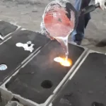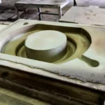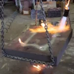
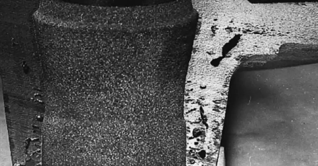
Sand casting defects are unwanted holes, missing sections, rough areas, shape changes, or cracks that form while a mold is filled or while the casting solidifies and cools. Common examples include gas porosity, shrinkage cavities, misruns, cold shuts, inclusions, mold or core shift, surface defects, warpage, and hot tears.
Some defects are visible as soon as the casting is cleaned. Others remain below the surface until machining exposes them. Their appearance and location can help you identify a likely defect type, but they cannot prove the root cause on their own.
What Are the Main Types of Sand Casting Defects?
The most useful way to learn the main types is to connect each name with what you may see and how it usually forms. The following groups cover the defects most often encountered without turning every variation into a separate category.
Gas Porosity: Pinholes, Blowholes, and Rounded Cavities
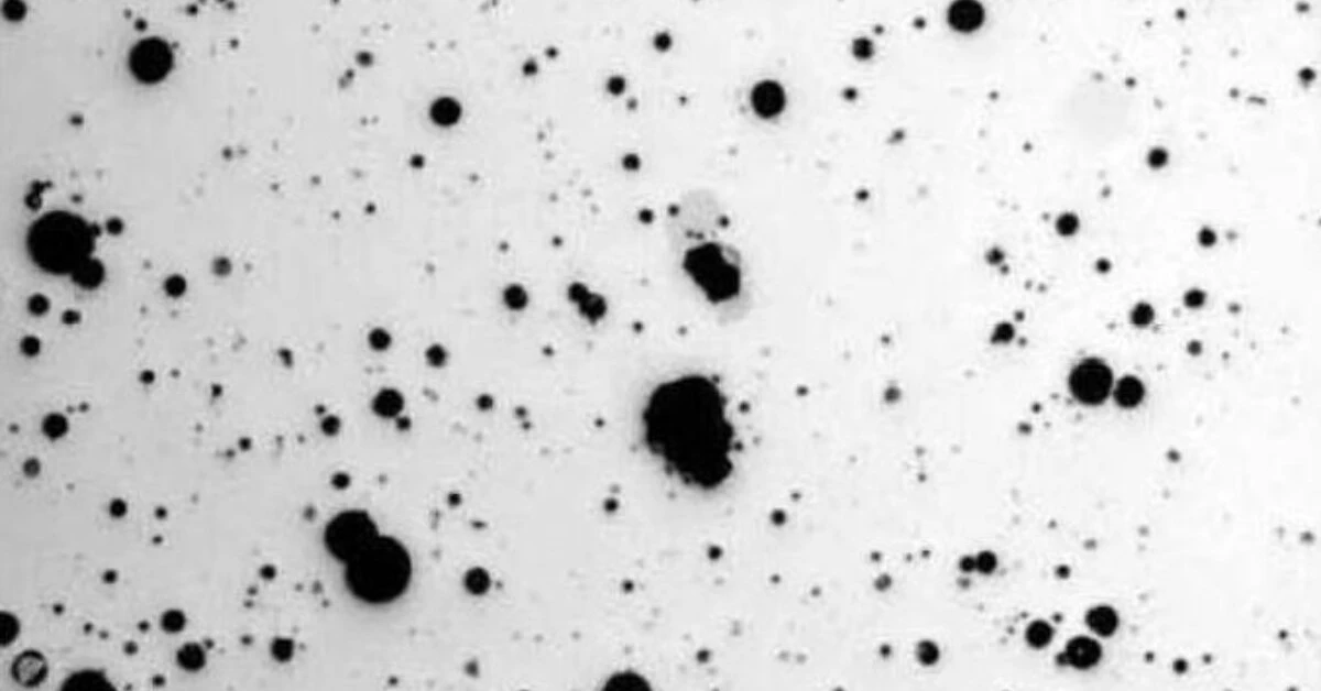
Gas porosity appears as holes at the surface, just below it, or inside the casting. Pinholes are small openings, while blowholes are larger cavities; both may be hidden until a surface is machined. When exposed, gas cavities often have smoother, more rounded walls than shrinkage cavities.
They form when gas becomes trapped as the metal solidifies. The gas may already be present in the melt, enter with turbulent flow, or be released by moisture, binders, or cores. Reducing the risk means controlling those gas sources, giving gas an effective escape path, and filling the mold more steadily.
Shrinkage Porosity and Cavities: Irregular Voids in Hot Areas
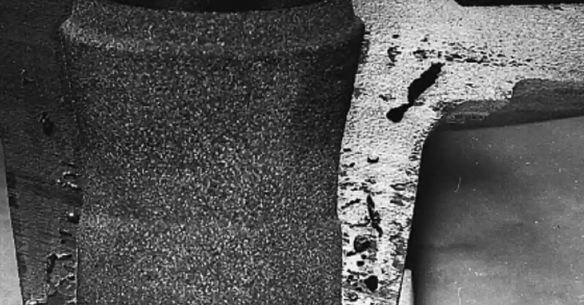
Shrinkage may appear as a rough internal cavity, a spongy cluster of small voids, or a sunken area on the surface. It is often associated with a thick section, a heavy junction, or another part of the casting that remains hot after nearby metal has started to solidify.
Metal contracts as it becomes solid. If liquid metal can no longer reach the last area to freeze, there is not enough material to replace the lost volume. Smoother wall transitions, fewer isolated heavy sections, and feeding and cooling designed around the actual geometry can reduce this risk.
Misruns: Missing or Incomplete Sections
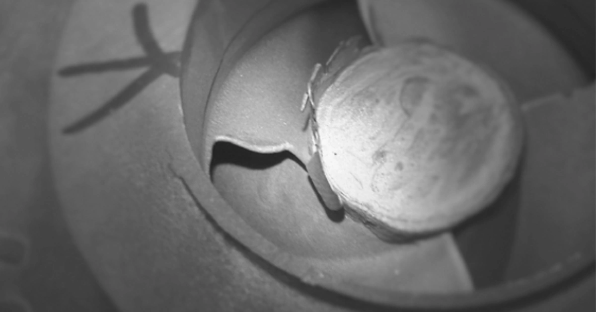
A misrun occurs when metal stops before the mold cavity is completely filled. The result may be a missing corner, a short edge, or an incomplete thin section, often ending in a rounded contour rather than a broken surface.
Long flow paths, thin walls, rapid heat loss, an interrupted pour, or leakage from the mold can all leave metal unable to reach the end of the cavity. Prevention begins by reviewing the part geometry and the route the metal must follow through the mold, rather than changing one pouring setting in isolation.
Cold Shuts: Seams Where Metal Flows Did Not Join
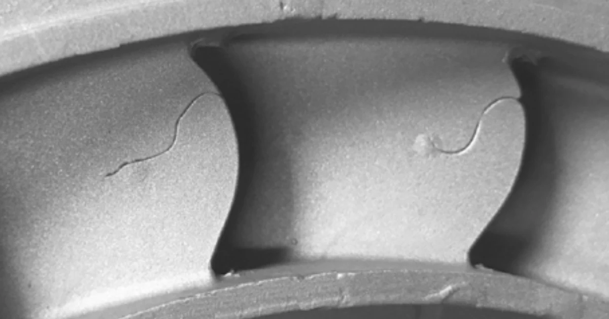
A cold shut, sometimes called a cold lap, appears as a line or rounded seam in an area that otherwise looks filled. It forms when two streams of metal meet but are no longer able to fuse into one continuous body.
The two fronts may have lost too much heat, met under an unfavorable filling pattern, or been separated by surface films. A better filling sequence and a flow path that allows the fronts to meet under suitable conditions can reduce the risk. Simply adding more heat is not a universal remedy because it can change oxidation, mold interaction, and solidification elsewhere.
Sand, Slag, and Oxide Inclusions: Material Trapped in the Metal
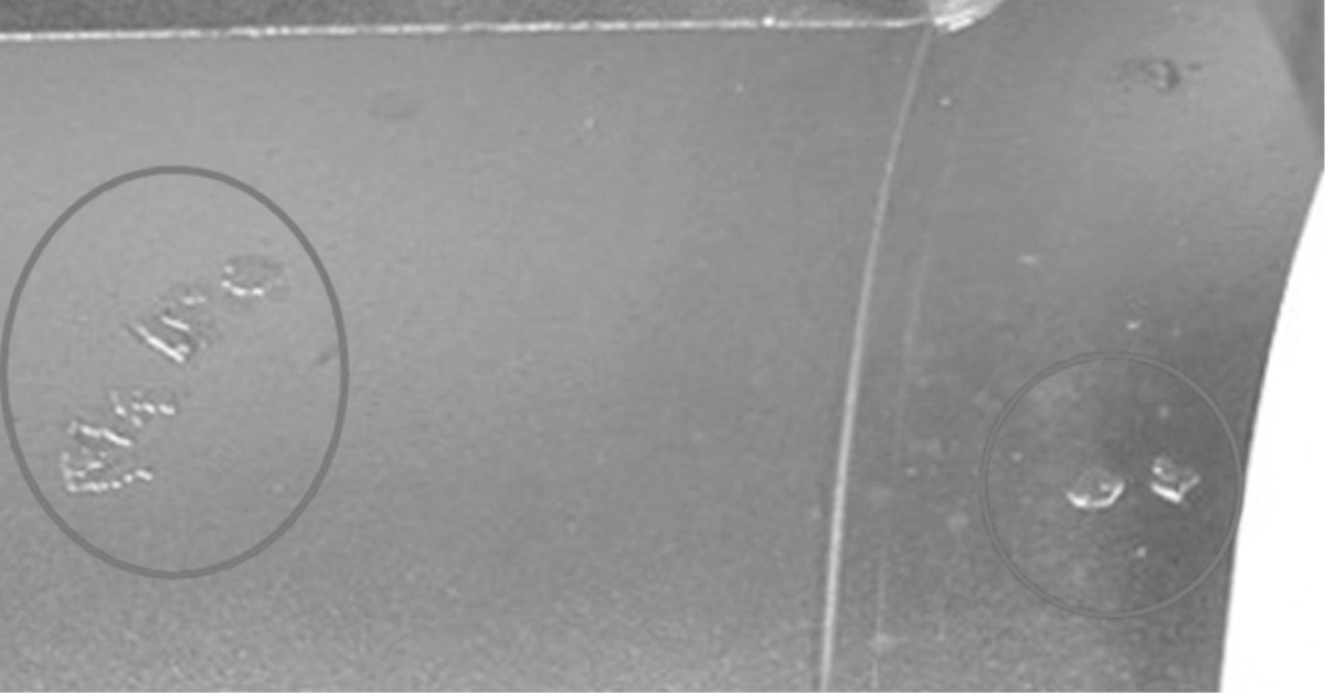
An inclusion is foreign material where solid metal should be. Sand may leave a rough pocket or remain embedded in the casting. Slag or oxide may appear as a nonmetallic patch, film, or irregular cavity. A photograph may show that an inclusion is present, but it may not reveal what the material is.
Sand can enter when a mold or core surface breaks down or is eroded by the incoming metal. Slag and oxide are more closely connected with melt handling and the pouring stream. Prevention therefore depends on whether the evidence points back to the mold, the core, the melt, or the way the cavity was filled.
Mold-Surface Defects: Cuts, Washes, Penetration, and Burn-On
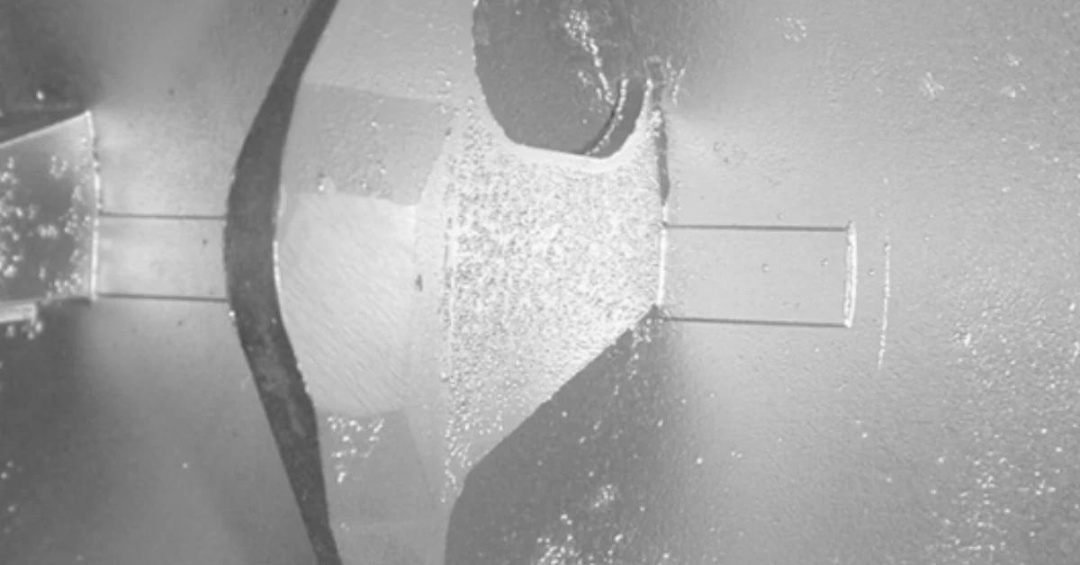
A cut or wash is a rough, eroded area left where flowing metal damages the mold face. Penetration and burn-on produce a hard, rough surface when metal enters the spaces between sand grains or adheres strongly to the mold material.
These problems are influenced by the condition and strength of the mold surface, the local metal flow, and the interaction between the alloy and the sand system. Stable mold preparation, suitable surface protection, and less damaging flow can help. The relevant controls differ between sand and binder systems used in sand casting, so one sand recipe cannot prevent every surface defect.
Mold Shift and Core Shift: Features That Move Out of Position
Mold shift commonly leaves a step where the two mold halves meet. Core shift moves a hole, passage, or other internal feature away from its intended position. The casting may look complete, yet the two sides or the internal geometry no longer line up correctly.
These defects point toward alignment, location, support, or movement during mold assembly and pouring. Secure mold closure and correctly supported cores reduce the risk, but dimensional measurement is normally needed to show how far a feature has moved.
Flash, Swell, and Warpage: Extra Metal or a Changed Shape
Flash or a fin is a thin projection of extra metal that enters a joint or gap in the mold. A swell is a broader bulge caused when the mold wall yields. Warpage changes the overall shape as different parts of the casting contract by different amounts.
Good mold closure helps control flash, while a stable mold limits swelling. Warpage requires a wider look at part geometry, support, and cooling. Removing a fin may restore an edge, but it will not correct a surface or axis that has distorted out of position.
Hot Tears and Cracks: Lines Formed During or After Cooling
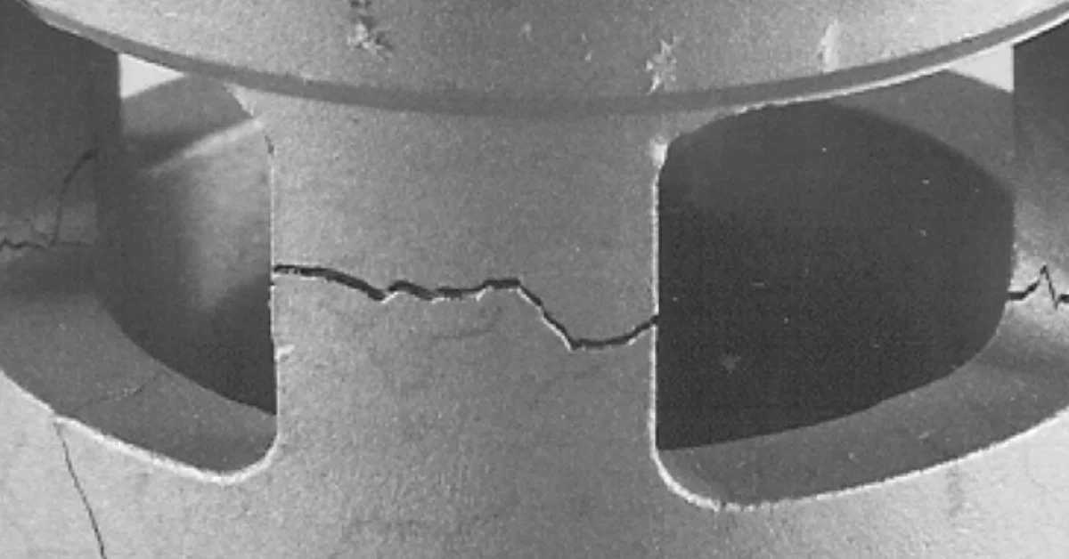
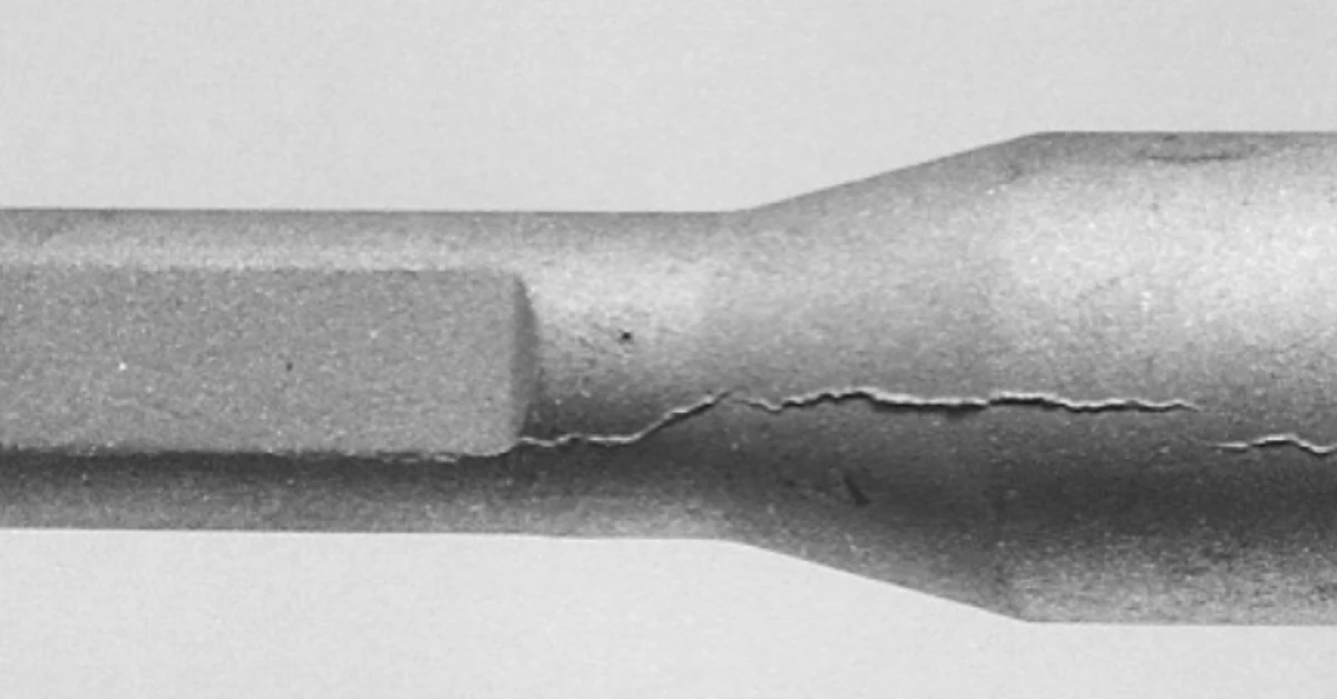
A hot tear is an irregular or branching crack that forms while the casting is still weak late in solidification. It develops when the metal tries to contract but is strongly restrained, often near an abrupt change in section or another area with uneven cooling.
Not every crack-like line is a hot tear. Cracks may also form later during cooling, handling, heat treatment, or machining, and a line in the mold can sometimes be copied onto the casting surface. The stage at which the line first appears helps direct the investigation. Gradual section changes, useful radii, controlled restraint, and more even cooling can reduce hot-tear risk within the wider sand casting process.
For more casting defects and their possible cause & corrections, please see Investment Casting Org’s Defects List
How Can You Tell Similar Sand Casting Defects Apart?
Start with the visible difference that changes the likely formation mechanism. Then use location and production stage to decide what to check next. This is more reliable than attaching the same long list of possible causes to every defect.
Gas Porosity vs. Shrinkage
Gas cavities commonly tend to be smoother and more rounded. That pattern makes gas sources and escape paths useful first questions. Shrinkage cavities are more often rough, irregular, or spongy and may occur near a heavy section or local hot spot. That pattern directs attention toward feeding and solidification.
These are tendencies, not a visual diagnosis. Both defects can be internal, and machining can expose either one. An illustrated review of defects in sand-mold cast irons also shows why appearance and process causes can overlap; its material-specific findings should not be treated as rules for every casting.
Cold Shut vs. Misrun
A misrun leaves part of the intended shape missing because the metal stopped too soon. A cold shut leaves a seam because metal reached the area in separate streams that did not fully join. If you see a missing section, trace where filling ended. If the shape is present but divided by a line, examine where the streams met.
The two defects can share conditions such as thin sections, heat loss, or an unfavorable flow path. The difference in the result tells you which event to investigate first; it does not mean one cause can be confirmed from appearance alone.
How Are Sand Casting Defects Found and Checked?
Visible surface defects can often be found during cleaning and visual inspection. Dimensional measurement is more useful when a parting-line step, shifted passage, distorted surface, or other shape error must be compared with the intended geometry.
Some cavities remain below the original surface and become visible only after machining. Cracks or other discontinuities that open to a suitable, clean, nonporous surface may be examined with liquid penetrant testing. ASTM E165/E165M-23 covers the penetrant examination method, but it does not provide one acceptance limit for every casting.
When the concern is internal, radiographic or ultrasonic inspection may be considered. A specified leak or pressure test answers a different question: whether the part performs its sealing function under the stated test conditions. The material, thickness, geometry, likely defect orientation, and purpose of the check all affect which method is appropriate.
Does Finding a Defect Mean the Casting Must Be Rejected?
No. Finding an indication, identifying the likely defect, and deciding whether the part is acceptable are three different steps.
A shallow mark on a nonfunctional surface does not have the same consequence as a cavity crossing a sealing face. A shifted hole can prevent assembly even when the metal is otherwise sound, while a crack in a loaded area can raise a structural concern. Acceptance therefore depends on the defect’s location and extent, the part’s material and intended use, and the drawing or specification that applies.
A general article can help you recognize a defect and choose a sensible next check. It cannot supply one allowable size, one inspection plan, or one repair decision for every sand casting.
If your next question is whether a new component should use sand casting or another manufacturing route, the sand casting service page explains the project-evaluation path.