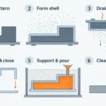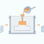
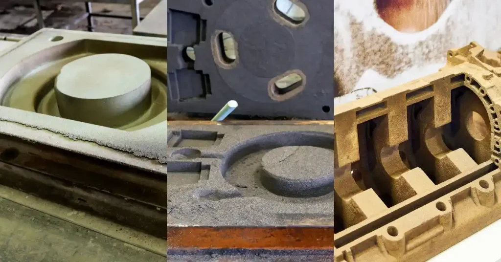
Sand casting materials are the materials that form a sand mold and its cores: a base sand or aggregate, a binder that holds the grains together, and any additives or coatings needed for the process. Cores use their own sand-and-binder system to create internal passages or other features that the external mold cannot form.
The metal poured into the mold is a separate material system. Alloy, pouring conditions, part geometry, production volume, surface requirements, dimensional requirements, and inspection needs all influence the mold and core system. This is why there is no single “best” casting sand or universal mixture for every part.
What Are Sand Casting Materials?
A sand mold is more than loose sand packed around a pattern. It is a controlled material system in which each component has a different job.
| Component | Main function | What must be evaluated |
| Base sand or aggregate | Forms the granular structure of the mold or core and withstands contact with molten metal | Grain size and distribution, grain shape, thermal behavior, permeability, density, binder compatibility, and supply consistency |
| Binder | Holds the grains together so the mold or core can be formed, handled, and poured | Binder chemistry, moisture or curing method, working time, strength, gas generation, storage, shakeout, and reclamation |
| Additives and mold coatings | Modify selected properties or the mold-metal interface | Compatibility, application consistency, drying or curing, gas behavior, surface requirements, and process control |
| Core system | Forms internal cavities, passages, or undercuts | Core strength, dimensional response, gas flow, storage, setting, collapsibility, and removal after casting |
These components work as a system. Changing the grain distribution can affect permeability and binder demand. Changing the binder can affect strength, gas generation, curing, and shakeout. A coating may improve the mold-metal interface, but it cannot compensate for an unsuitable or poorly controlled base system.
Patterns are also part of the tooling route, but they are not the subject of this guide. Likewise, an alloy list answers a different question: what metal can be poured, not what material forms the mold.
Also Read: What is Sand Casting
Base Sands: Four Common Choices
Silica is the most common base sand identified in foundry references because it is widely available and relatively economical. Chromite, zircon, and olivine are specialty aggregates considered when their thermal or physical behavior better fits a particular requirement.
The material name alone is not enough to select a route. Foundries also evaluate the grade, source, grain shape, grain-size distribution, binder system, coating, reclamation method, alloy, pouring conditions, and casting geometry.
| Base sand | General industry role | Why it may be considered | What to confirm for a project |
| Silica | Common general-purpose base aggregate | Availability, cost, and established molding practice | Grain characteristics, thermal expansion, permeability, binder compatibility, reclaimed-sand control, and the required surface and dimensions |
| Chromite | Specialty aggregate used in selected mold or core applications | Different thermal and physical behavior from silica may help in demanding mold-metal interface conditions | Whether it is needed throughout the mold or only in selected areas, plus grading, binder/coating compatibility, reclamation, availability, and cost |
| Zircon | Specialty aggregate considered for selected thermal and dimensional requirements | Its expansion behavior may be useful when mold stability needs closer control | Grain characteristics, binder compatibility, expected heat input, supply, reclamation, and whether the benefit justifies the added process cost |
| Olivine | Specialty alternative available for selected foundry systems | Different expansion and physical behavior from silica may suit some applications | Source and grading, alloy and binder compatibility, expected thermal conditions, reclamation, and supply consistency |
This table is a screening framework, not a performance ranking. A specialty aggregate may be used in a facing layer, in a core, in a local high-risk area, throughout a mold, or not at all. The right decision depends on the complete process rather than the sand name.
Grain Size Is a Tradeoff, Not a Standalone Specification
Grain size and grain-size distribution influence the pore structure at the mold surface. A finer or more densely packed system may support a smoother interface, but it can also change permeability and binder demand. A coarser or more open structure may allow gases to move differently while creating a different risk of metal entering surface pores.
Grain shape, compaction, binder condition, metal pressure, and coating all affect the result. For that reason, a grain-fineness value should be reviewed with the rest of the mold system and the casting requirements.
Binder Systems Define How the Sand Holds Its Shape
Base sand provides the aggregate; the binder determines how those grains stay together. Foundries use several binder families, and each family contains different formulations and control methods.
| Binder system | How it works at a high level | Main engineering considerations |
| Clay-bonded green sand | Bentonite clay and controlled moisture give the sand cohesion in its moist, uncured condition | Moisture, clay condition, compactability, strength, permeability, sand preparation, and consistency through reuse |
| Chemically bonded sand | An organic or inorganic reaction hardens the mold or core; no-bake is one ambient-curing category | Mixing and working time, cure and strip time, handling strength, gas generation, storage, thermal response, shakeout, and reclamation |
| Sodium silicate-bonded sand | An inorganic sodium silicate system is hardened through a selected curing route | Actual hardening method, working time, moisture sensitivity, retained strength, collapsibility, cleaning, and reclamation |
“Green” describes the moist, uncured condition and the material’s green strength; it does not mean that the sand is green in color. Clay, moisture, grain distribution, compaction, and additives must remain within a controlled operating window.
Chemically bonded systems should not be treated as a single resin process. Binder chemistry and curing route affect how long a mold or core remains workable, how it develops strength, how it behaves during pouring, and how readily it breaks down afterward. No-bake, cold-box, warm-box, shell, and other terms refer to different systems and should not be used interchangeably.
Sodium silicate is an inorganic binder category rather than a universal substitute for organic resin. Its suitability depends on the curing route, part geometry, handling requirements, shakeout, cleaning, reclamation, and the foundry’s process controls.
Additives, Coatings, and Core Materials
Additives may be mixed into a sand system to modify flowability, expansion behavior, moisture response, or the mold-metal interface. Their effect depends on the formulation and operating conditions. A generic additive name does not establish the final behavior of the mold.
Mold and core coatings form a refractory layer at the surface that contacts molten metal. A compatible, consistently applied coating may help manage metal penetration and surface condition. Its chemistry, layer thickness, drying, adhesion, and compatibility with the sand, binder, alloy, and pouring conditions still need to be controlled. Coating is one part of the system, not a substitute for suitable sand preparation and mold integrity.
Cores deserve separate attention because they must hold internal geometry during handling and pouring, allow gases to be managed, and then be removed from the casting. A core may use a different sand and binder system from the surrounding mold. Internal access, thin or long passages, section changes, storage time, core setting, and the planned cleaning method all affect the choice.
How the Material System Affects Casting Results
Mold materials influence casting results, but they do not act alone. Gating, feeding, melt quality, pouring practice, mold preparation, core setting, solidification, cleaning, machining, and inspection can contribute to the same visible problem. A useful review looks at the complete route before assigning a defect to one material variable.
Surface Condition and Metal Penetration
Liquid metal can enter pores or cracks at the mold or core surface and leave a rough, adherent layer. Grain distribution, compaction, binder condition, metal pressure, sand expansion, and coating can all influence this mechanism.
A finer sand or a refractory coating may be part of the response, but neither is an automatic fix. The foundry still needs to examine the source of the open pore structure or surface damage and confirm that the proposed change remains compatible with gas flow, strength, and the rest of the process.
Gas Flow, Permeability, and Strength
Permeability describes how gases pass through the mold material. Low gas flow can contribute to pressure buildup or gas-related defects, while a very open surface may increase penetration risk under some conditions.
The mold also needs enough strength to survive pattern withdrawal, handling, core setting, and pouring. More binder or higher strength is not always better: it can change gas generation, collapsibility, cleaning, and reclamation. Permeability and strength therefore need to be evaluated together with venting, compaction, moisture or cure, geometry, and pouring conditions.
Thermal Expansion and Dimensional Behavior
Base sands and binders respond to heat. Expansion, restraint, softening, core size, mold geometry, and the amount of metal—and therefore heat—inside the mold can influence final dimensions.
Published experiments on cylindrical steel castings have shown that sand type, binder system, and core-controlled heat input affected dimensions within that specific setup. The practical lesson is not a universal correction factor. It is that dimensional allowances and critical features should be validated for the actual alloy, geometry, tooling, and molding route.
Collapsibility, Shakeout, and Cleaning
After solidification, the mold must break away and the cores must be removed. Binder chemistry, thermal exposure, core geometry, internal access, and retained strength affect how much shakeout, blasting, cutting, or other cleaning work is required.
For a part with internal passages, “the core can be made” is only half the question. The process plan should also explain how the core will be removed, how residual material will be assessed, and whether the cleaning route can reach the required surfaces without damaging the casting.
Reclamation and Process Consistency
Foundries may reclaim molding and core sands through mechanical or thermal methods. Reclamation can reduce new-sand demand, but reused material changes through heat exposure, abrasion, residual binder, fines, and contamination.
The useful question is not simply whether sand can be reused. It is how sand streams are separated, conditioned, tested, and blended with new material so the system remains stable. The appropriate controls depend on the binder, alloy, equipment, casting requirements, and local environmental obligations.
How to Evaluate a Sand System for a Part
Start with the casting requirements rather than a preferred sand name.
- Define the alloy and pouring conditions.Provide the material grade and applicable specification. The mold system must be reviewed against the expected thermal and chemical conditions rather than a generic “steel,” “iron,” or “aluminum” label.
- Review the geometry and core demand.Identify section changes, long or thin features, internal passages, undercuts, inaccessible cavities, and areas that concentrate heat or metal pressure.
- State the surface and dimensional requirements.Mark critical dimensions, datums, machining allowances, casting tolerance references, surface expectations, and areas where aggressive cleaning is unacceptable.
- Define quantity and production needs.Prototype validation, repeat batches, and higher-volume programs may justify different tooling, molding, coremaking, and control routes.
- Agree on inspection and evidence.Define material certification, dimensional reporting, visual standards, nondestructive testing if required, sampling, traceability, and how the proposed mold and core route will be validated.
Questions to Ask a Foundry
| Question | Why it matters |
| What molding and coremaking route is proposed for this drawing and quantity? | Establishes the actual process being evaluated instead of relying on a general service label |
| What base sand and binder categories are proposed, and why? | Connects material choice to alloy, geometry, surface, dimensions, and production requirements |
| Which sand or mold properties are controlled, and by what approved methods? | Shows how the foundry maintains a stable process without assuming that every facility uses the same tests or limits |
| How will complex cores be stored, set, vented, removed, and checked? | Addresses internal geometry, gas management, dimensional risk, and residual-sand concerns |
| Are coatings or facing materials proposed in selected areas? | Identifies local mold-metal interface controls and their application requirements |
| How are reclaimed and new sand managed in this process? | Helps assess consistency, contamination, fines, residual binder, and supply control |
| What sample, first-article, or trial validation is appropriate? | Aligns tooling and process decisions with the cost of change and the risk of repeat production |
| How will process or material changes be communicated? | Supports traceability when a foundry changes sand source, binder, coating, reclamation practice, or production route |
The goal is not to force every supplier into one material system. It is to make the proposed route visible enough to evaluate against the drawing and acceptance requirements.
Preparing a Sand Casting RFQ
A useful RFQ includes a controlled drawing or 3D model, the alloy and applicable specification, estimated quantities, critical dimensions and surfaces, machining requirements, inspection and documentation needs, and the expected delivery schedule. Internal passages and difficult-to-clean areas should be identified explicitly.
For a project-specific review, submit those requirements together so the proposed mold, core, finishing, and inspection route can be evaluated as one manufacturing plan.
FAQs
What is casting sand made of?
Casting sand usually starts with a refractory base aggregate and a binder. Depending on the process, the system may also include controlled moisture, additives, a mold or core coating, and separate core materials. There is no universal recipe because the required combination depends on the alloy, geometry, molding route, and quality requirements.
What is the difference between green sand and resin-bonded sand?
Green sand is a moist, clay-bonded molding system used in its uncured condition. Resin-bonded sand hardens through a specific chemical reaction. Each category has multiple formulations, and the practical differences include working and curing behavior, strength, gas generation, storage, shakeout, cleaning, and reclamation.
Is silica sand always the best choice?
No. Silica is common because it is widely available and economical, but its grain characteristics and thermal expansion still need to fit the casting. Chromite, zircon, olivine, or a localized specialty-sand application may be evaluated when different thermal or physical behavior is needed. Cost, supply, binder compatibility, and process control remain part of the decision.
Can foundry sand be reused?
Yes, foundry sand may be mechanically or thermally reclaimed and returned to a controlled process. Reuse is not automatic: heat, abrasion, residual binder, fines, and contamination can change the material. The foundry must define how reclaimed sand is separated, tested, conditioned, and blended for the selected system.
Are sand casting materials the same as metals used for sand casting?
No. Mold and core materials create the temporary shape into which metal is poured. The cast metal has its own chemistry, melting, solidification, heat-treatment, machining, and inspection requirements. A project review needs to confirm both the alloy capability and the mold/core route.