A pump housing can be straightforward on the outside and difficult to manufacture inside. Curved passages may require several sand cores, tooling, and careful assembly. 3D printed sand molds and cores change how that shape is made—but where do they actually save time and money?
What Are 3D Printed Sand Molds?
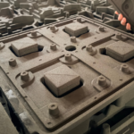
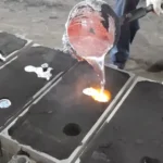
3D printed sand molds are casting molds built directly from digital files, usually by selectively bonding layers of sand with a liquid binder. A foundry pours molten metal into the prepared mold, allows it to solidify, and removes the sand to release the casting.
The mold forms the outside of the part. A sand core occupies space inside the mold where metal must not go, creating a hollow section or internal passage. Both can be printed.
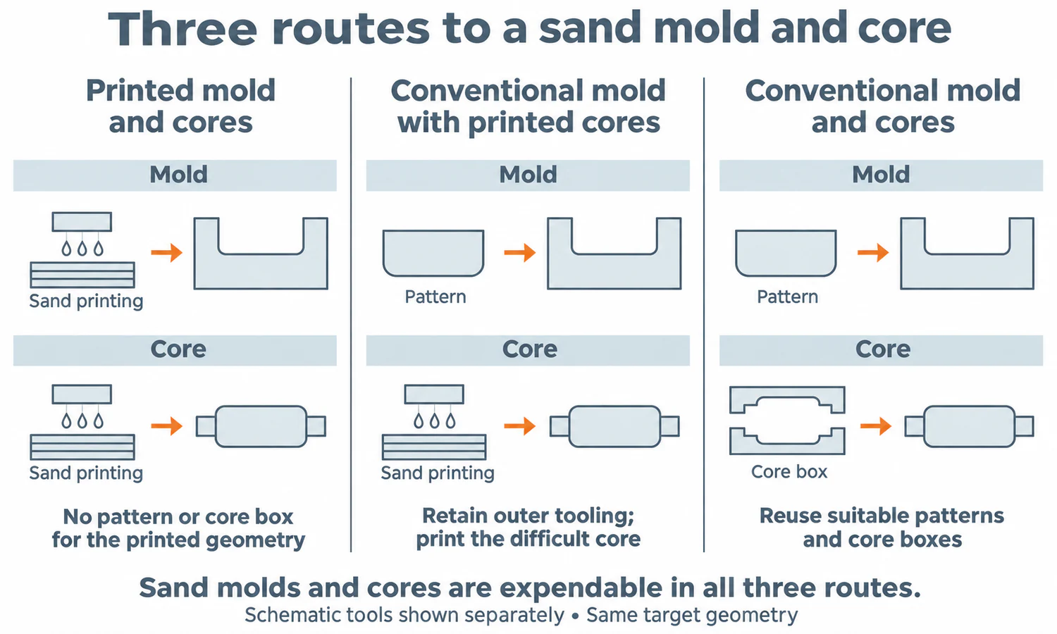
In conventional sand molding, a reusable pattern creates the mold cavity, while a core box shapes the core. Direct sand printing removes the need for these tools wherever the sand geometry is printed. The sand mold itself is still expendable: it is broken up after casting, even when some of the sand can be reclaimed.
Printing a plastic pattern is different. That printed pattern still has to be used to make a sand mold. Direct metal printing is different again: it builds the metal component itself. Our casting vs. 3D printing comparison covers that broader choice.
How Does Sand 3D Printing Work?
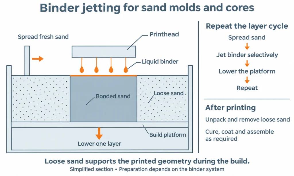
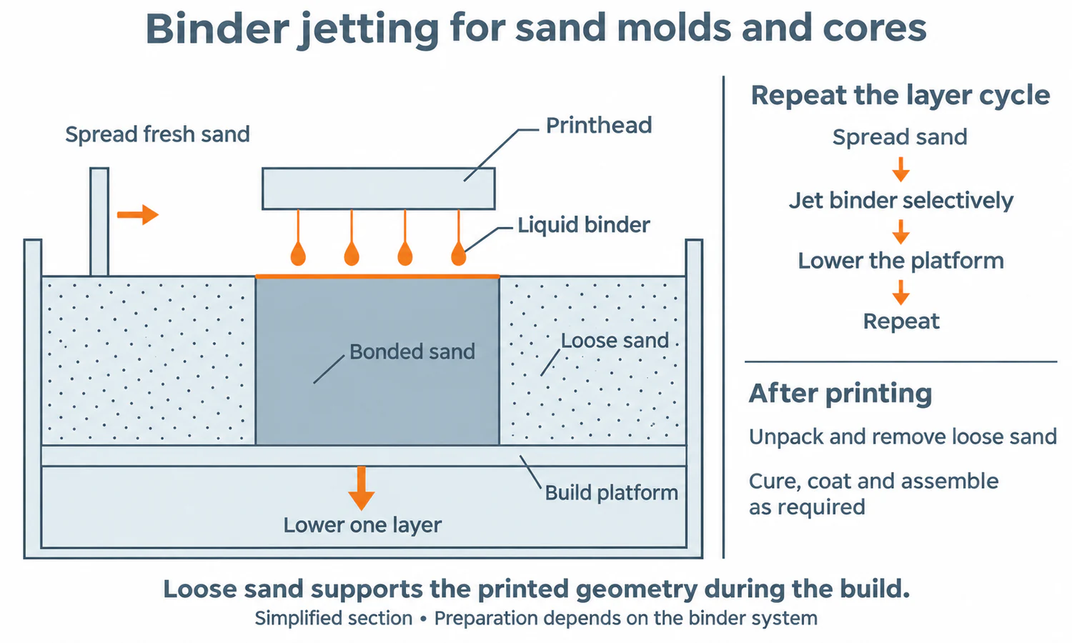
The most common industrial method is binder jetting. A recoater spreads a thin layer of sand across a build platform. A printhead deposits binder in selected areas, the platform lowers, and the cycle repeats. Loose sand surrounds and supports the bonded shapes during printing. ExOne explains this layer-by-layer process in its technology overview.
Before printing, the foundry turns the component design into a casting layout. This includes the mold cavity, cores, metal-entry channels, feeding features, and allowances for contraction and machining. A finished-part CAD file is therefore a starting point, rather than necessarily a ready-to-print mold file.
After printing, the molds and cores are unpacked and cleared of loose sand. Curing or thermal treatment depends on the binder system. Coating and assembly follow where required, before the mold is prepared for pouring.
Once metal enters the mold, the familiar foundry sequence continues: solidification, cooling, sand removal, cutting off the feed system, cleaning, and any specified heat treatment, Bearbeitung, Und Inspektion. Printing changes mold and core manufacture; it does not turn the printer into a complete casting line.
Why Use Printed Molds and Cores?
Complex Shapes and Internal Passages
A conventional pattern must come out of the sand without damaging the cavity. This influences draft angles, parting lines, and the way undercuts are formed. A printed mold has no pattern to withdraw, giving the designer more freedom over those features.
The larger benefit often lies inside the casting. Imagine a housing with a branching passage: making its core conventionally may require several pieces, each located and joined accurately. Printing can combine suitable pieces into one core, reducing joints and assembly work. Humtown’s application guide identifies core consolidation, complex geometry, missing tooling, and design changes as useful reasons to consider the process.
This matters because each core joint is also another place where positioning can vary. Removing a joint can simplify manufacture and help control passage geometry. The printed core still needs enough strength and support to survive handling and pouring.
A Pump-Impeller Example
In ExOne’s published Xylem case, an impeller core previously consisted of four separately made pieces that were glued together. Binder jetting produced it as one piece.
The reported cores measured 220 mm in diameter and 60 mm high. Their manufacturing time fell from seven days to 48 hours, with up to 480 cores accommodated in one build. The case also reports approximately 30% lower production costs for certain parts.
These are results from that application, and the two-day figure refers to core manufacture. The useful lesson is the mechanism: combining pieces removed assembly operations while allowing many cores to share a build. Printing earned its place by simplifying a difficult production step.
New Designs and Replacement Parts
For a prototype, avoiding pattern manufacture allows a design to reach casting sooner. A revised passage can be incorporated into the next print without modifying a physical core box.
The same advantage applies to an obsolete part whose tooling is missing. However, someone still has to establish the correct geometry, material, and drawing requirements. Scanning a worn component captures its present shape, which may include wear or distortion. Printing makes an approved replacement design easier to manufacture; it does not determine what that design should be.
Printed Molds vs. Conventional Sand Molds
There are three practical routes to compare. A foundry can print the mold and cores, retain conventional molding throughout, or use printed cores inside a conventionally made mold.
| Route | What it offers | Where it deserves consideration |
|---|---|---|
| Printed mold and cores | Avoids pattern and core-box manufacture for the printed geometry | New designs, missing tooling, complex low-volume parts |
| Conventional mold with printed cores | Keeps established outer-mold tooling while changing difficult internal features | Parts with a simple exterior and complicated passages |
| Conventional mold and cores | Reuses tooling over repeated production | Stable designs with suitable existing tooling and efficient molding cycles |
The hybrid route can be especially useful. If a housing’s exterior is already easy to mold, printing that entire mold may add little value. Printing only the difficult core directs the extra manufacturing expense toward the feature that needs it. It can also let a foundry test a revised internal passage while retaining suitable outer tooling.
Printed cores are used beyond prototypes. A 2023 voxeljet report on TEI’s Cadillac CELESTIQ work describes six aluminum underbody castings using 51 printed sand cores per vehicle. The cores were finished and coated before casting, and the castings had machined interfaces for assembly.
That example shows why “prototype only” is too narrow a description. Production use depends on the value of the geometry and the efficiency of the complete process.
What Affects Cost and Lead Time?
Tooling Cost and Order Quantity
Conventional molding usually has an initial tooling expense followed by repeated use of the same pattern and core boxes. Printed sand avoids that tooling expense, but each pour still consumes a newly manufactured mold and core package.
This changes the cost balance with quantity. For illustration, a hypothetical $6,000 tooling investment contributes $300 per casting across 20 accepted castings, but $30 across 200. These figures only demonstrate tooling allocation; they are not tooling quotes or total casting prices.
Once usable tooling already exists, its original purchase cost is normally a past expense for the next order. The comparison should then focus on remaining costs, such as repairs, modifications, mold production, and finishing. This is why printing may be attractive for a new small batch yet unnecessary for a repeat order of a simple, proven part.
Printing and Handling Costs
Sand and binder are only part of the bill. The printer’s build space, build height, packing arrangement, and operating time also matter. Several small cores may share a build efficiently; a bulky mold can occupy a large share of the machine even when its casting is relatively simple.
Cleaning, coating, assembly, and transport also deserve attention. A design that prints successfully but takes considerable effort to unpack may lose much of its apparent advantage. Conversely, a core that replaces several assembled pieces can save work after printing.
For a meaningful comparison, ask for the cost per accepted casting at the same delivery condition. A printed mold quote and a machined, inspected casting quote cover very different amounts of work.
Time to the Finished Part
The largest schedule gain often comes from removing the wait for new or revised tooling. Printer availability, curing, mold preparation, pouring schedules, cooling, machining, and testing still affect delivery.
Separate three milestones when reviewing a schedule: molds ready, raw castings ready, and finished parts ready. A fast printing cycle helps only if it shortens the route to the milestone you actually need.
There is no reliable universal break-even quantity. A difficult core may justify printing in repeated production, while a simple mold made from existing tooling may favor conventional molding even at a modest order size.
Materials, Accuracy, and Design Limits
Sand, Binders, and Casting Alloys
Industrial systems use foundry sands with compatible binders, including furan, phenolic, and inorganic systems. Aluminum, iron, steel, and other alloys can be cast using appropriately selected printed molds and cores. The sand-and-binder combination must suit the metal, geometry, and casting conditions.
Conventional no-bake sand casting also uses chemically bonded sand. The distinguishing feature of binder jetting is how the geometry is built, rather than simply the presence of resin in the sand.
Surface Finish and Tolerances
A printed mold’s layer height is not the finished casting’s dimensional tolerance. For example, voxeljet’s May 2020 ODB data sheet lists a 300 micrometer layer height—0.30 mm—for that silica-sand/furan process. This is a printing parameter, not a promise that every resulting metal dimension will fall within ±0.30 mm.
Sand grain size, layer orientation, coating, mold assembly, and metal contraction all affect the result. Bearing seats, sealing faces, and precision mounting features may still need machining. Identify these surfaces on the drawing so the foundry can plan the allowance and measurement method.
Cleaning and Casting Constraints
Loose sand must be removed before pouring, and cores must be removable after casting. Long, narrow or branching spaces can make cleaning difficult. A 2023 study in the International Journal of Metalcasting explains how limited access and the fragility of printed sand complicate cleaning, and how dividing molds into accessible sections can help.
That creates a practical tradeoff: consolidating everything into one print reduces assembly, but splitting the mold may make it easier to clean reliably. The best division is the one that works through the whole process.
Metal still needs to fill the cavity and solidify soundly. Thick junctions, thin walls, feeding paths, and gas escape remain design concerns. Printed geometry can help position these features, but it cannot replace their engineering. Our guide to Steigleitungen beim Gießen explains why filling a cavity successfully does not guarantee adequate feeding during solidification.
How to Evaluate a Part for Sand Printing
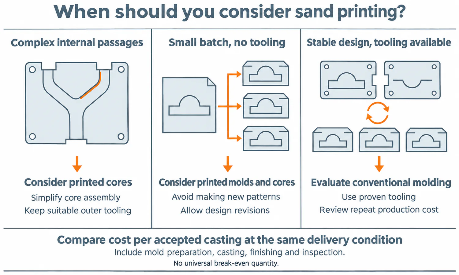
Start with the difficulty in the existing or proposed route. Is it the cost of new tooling, a passage that requires many core pieces, frequent design changes, or an urgent replacement? That answer helps determine whether to print the entire mold package or only selected cores.
Provide the component CAD model, drawing, alloy, quantity, required delivery condition, and critical surfaces. Include information about existing tooling. Then establish who will design the casting layout and whether the supplier is delivering printed sand, raw castings, or finished components.
This gives the foundry a useful comparison to make: which route can produce the required part with the least total work, acceptable quality, and a realistic delivery schedule?
Abschluss
3D printed sand molds and cores are most valuable when tooling or complex core assembly is the obstacle. Compare full printing, printed cores, and conventional molding at the finished-part level. The right choice depends on the work saved across the casting process, not the printer alone.
Häufig gestellte Fragen
What Is a 3D Printed Sand Mold?
A 3D printed sand mold is a casting mold built layer by layer from a digital file, usually by binder jetting. The mold forms the outside of the part, while printed sand cores create hollow sections or internal passages. Both can be printed without patterns or core boxes.
How Fast Is Sand 3D Printing?
The biggest schedule gain comes from removing the wait for new or revised tooling. In the published Xylem impeller case, core manufacture fell from seven days to 48 hours. The printing cycle itself is not the delivery schedule—separate the milestones for molds ready, raw castings, and finished parts.
Is 3D Printed Sand Cheaper Than Conventional Tooling?
There is no universal answer. Printing avoids tooling expense, but every pour consumes a newly manufactured mold and core package. For illustration, a $6,000 tooling investment contributes $300 per casting across 20 parts but $30 across 200. A hybrid route with printed cores inside a conventional mold is often the best value.
What Metals Can Be Cast With Printed Sand Molds?
Aluminum, iron, steel, and other alloys can be cast using appropriately selected printed molds and cores. The sand-and-binder combination—furan, phenolic, or inorganic—must suit the metal, geometry, and casting conditions.
What Tolerances Can 3D Printed Sand Molds Achieve?
The printing layer height is not the casting’s dimensional tolerance. For one voxeljet silica-sand/furan system the layer height is 300 micrometers (0.30 mm), but sand grain size, coating, mold assembly, and metal contraction all affect the result. Critical features may still need machining.
When Should I Use 3D Printed Sand Molds?
Consider printing when the cost of new tooling, a passage requiring many core pieces, frequent design changes, or an urgent replacement is the main obstacle. Compare full printing, printed cores only, and conventional molding at the finished-part level.