Feinguss can produce complex parts with good dimensional control and surface quality, but defects can begin at many stages: wax pattern making, shell building, melting, pouring, solidification, heat treatment, and finishing.
A visible defect is therefore only the result. Finding the real cause means tracing it back through the process.
This guide explains the most common investment casting defects, how they form, how similar defects differ, and where a foundry should look when troubleshooting them.
What Counts as an Investment Casting Defect?
A casting defect can take many forms.
Metal may fail to fill part of the cavity. A void may develop inside a heavy section during solidification. Ceramic or oxide material can become trapped in the metal. A shell crack can create an unwanted metal fin. The casting can also be metallurgically sound but distorted enough to miss the drawing.
Das Investment Casting Institute casting defect atlas includes filling defects, shrinkage, gas, inclusions, shell-related defects, cracks, distortion, and damage introduced during finishing.
The useful lesson is simple:
A defect name describes what we see. It does not automatically tell us why it happened.
Common Investment Casting Defects at a Glance
| Defect | Typical Appearance | Main Area to Investigate |
|---|---|---|
| Non-fill / Misrun | Missing metal, often with rounded edges | Filling, temperature, gating |
| Cold Shut | Seam where two metal fronts failed to fuse | Metal flow and temperature |
| Shrinkage Porosity | Irregular internal or surface cavities | Solidification and feeding |
| Gas Porosity | Smooth, rounded cavities | Melt quality, gas, burnout, turbulence |
| Non-Metallic Inclusion | Ceramic or foreign material trapped in metal | Shell, cleanliness, tree assembly |
| Oxide / Slag Inclusion | Films or non-metallic material | Melting and turbulent flow |
| Finning | Thin unwanted metal projections | Shell cracking |
| Rough Surface / Penetration | Grainy or sandpaper-like surface | Prime coat and shell surface |
| Hot Tear / Crack | Jagged or linear fracture | Solidification, contraction, later processing |
| Distortion | Casting geometry moves out of tolerance | Wax, cooling, heat treatment, handling |
These categories are useful for identification, but defects that look similar can still have different root causes.
Non-Fill and Cold Shuts: Problems During Mold Filling
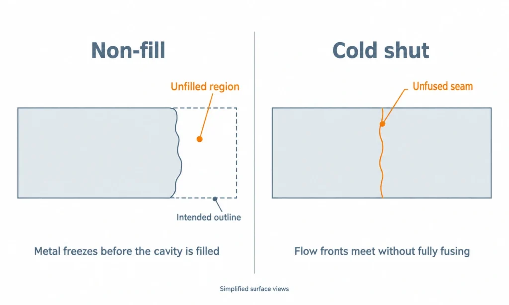
A non-fill, or misrun, occurs when molten metal freezes before the ceramic cavity is completely filled.
Thin walls, long flow paths, low metal temperature, low shell temperature, interrupted pouring, or unsuitable gating can all contribute. The Investment Casting Institute lists these among the common causes of non-fill.
A cold shut happens when separate metal fronts reach the same area but fail to fuse completely, leaving a visible seam.
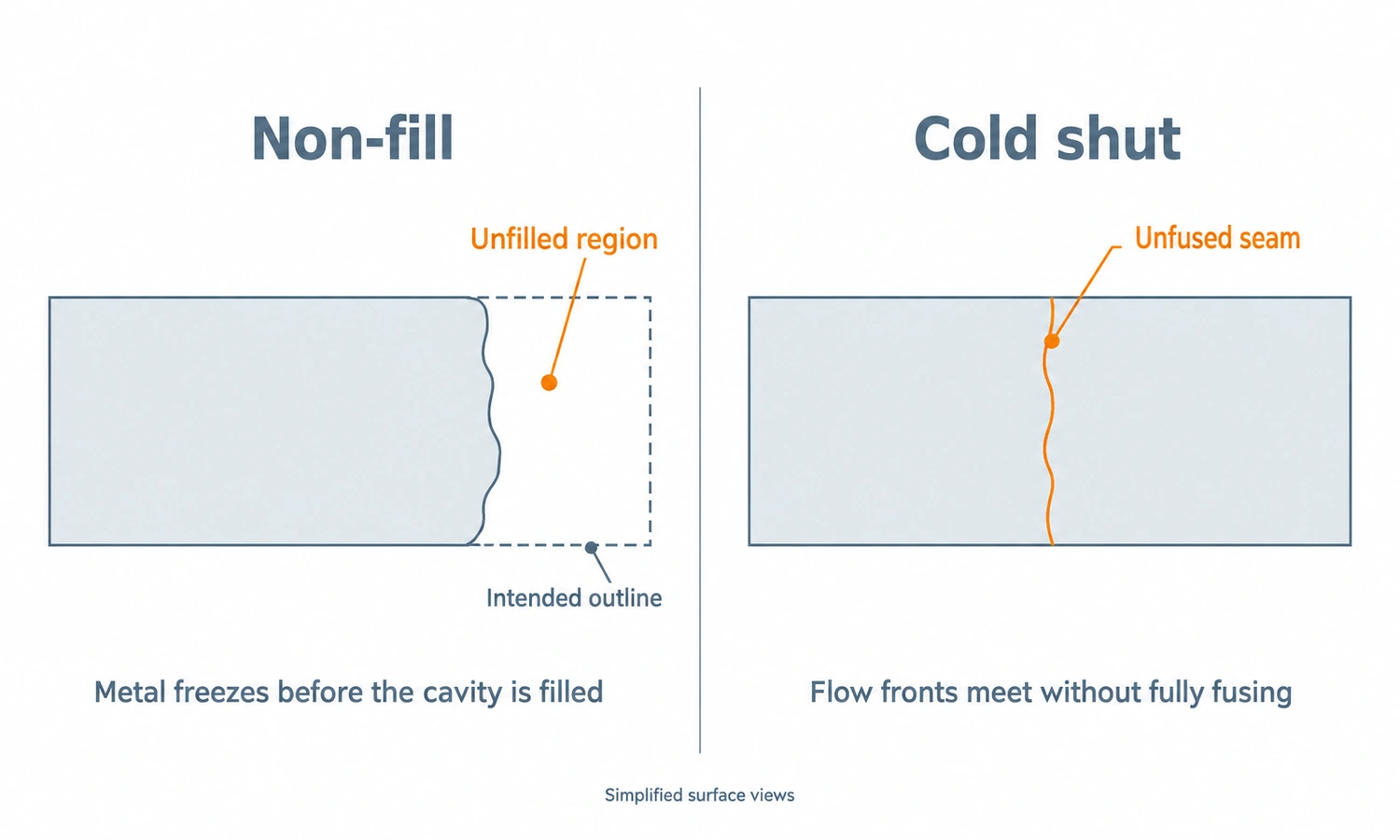
Both defects point toward filling, but simply increasing pouring temperature is not always the right fix. If the gate is poorly located or the flow path is too long, extra heat may only hide the real problem.
When we investigate incomplete filling, we look at the whole path from gate to cavity: section thickness, runner layout, metal temperature, shell preheat, flow distance, and alloy fluidity.
For difficult geometries, casting simulation can help identify areas where metal is likely to lose temperature before filling is complete.
Shrinkage Porosity: Problems During Solidification and Feeding
Metal contracts as it solidifies.
If a region remains liquid after the surrounding metal and can no longer receive additional feed metal, a shrinkage cavity can form.
These defects are often irregular and appear in heavy sections, abrupt wall-thickness transitions, or isolated hot spots. ICI’s guidance on internal shrinkage similarly links the defect to inadequate feeding and late-solidifying regions.
A common example is a heavy boss connected to a thin wall. The thin section can freeze first and cut off the liquid-metal path while the boss is still contracting.
Corrective action may involve gate size and location, feeding layout, tree orientation, local geometry, shell temperature, or cooling conditions.
The aim is not simply to add more metal. It is to keep liquid metal connected to the regions that still need feeding.
This is why gating design and solidification have to be considered together.
Gas Porosity: Smooth Cavities Caused by Trapped Gas
Gas porosity usually appears smoother and rounder than shrinkage.
Possible sources include turbulent filling, trapped air, dissolved gas, incomplete wax burnout, outgassing from cores or binders, moisture, and poor shell permeability. ICI lists these mechanisms in its guidance on gas defects.
Location and shape help with diagnosis.
Rounded cavities near areas where gas can become trapped point in a different direction from irregular pores concentrated in a heavy hot spot.
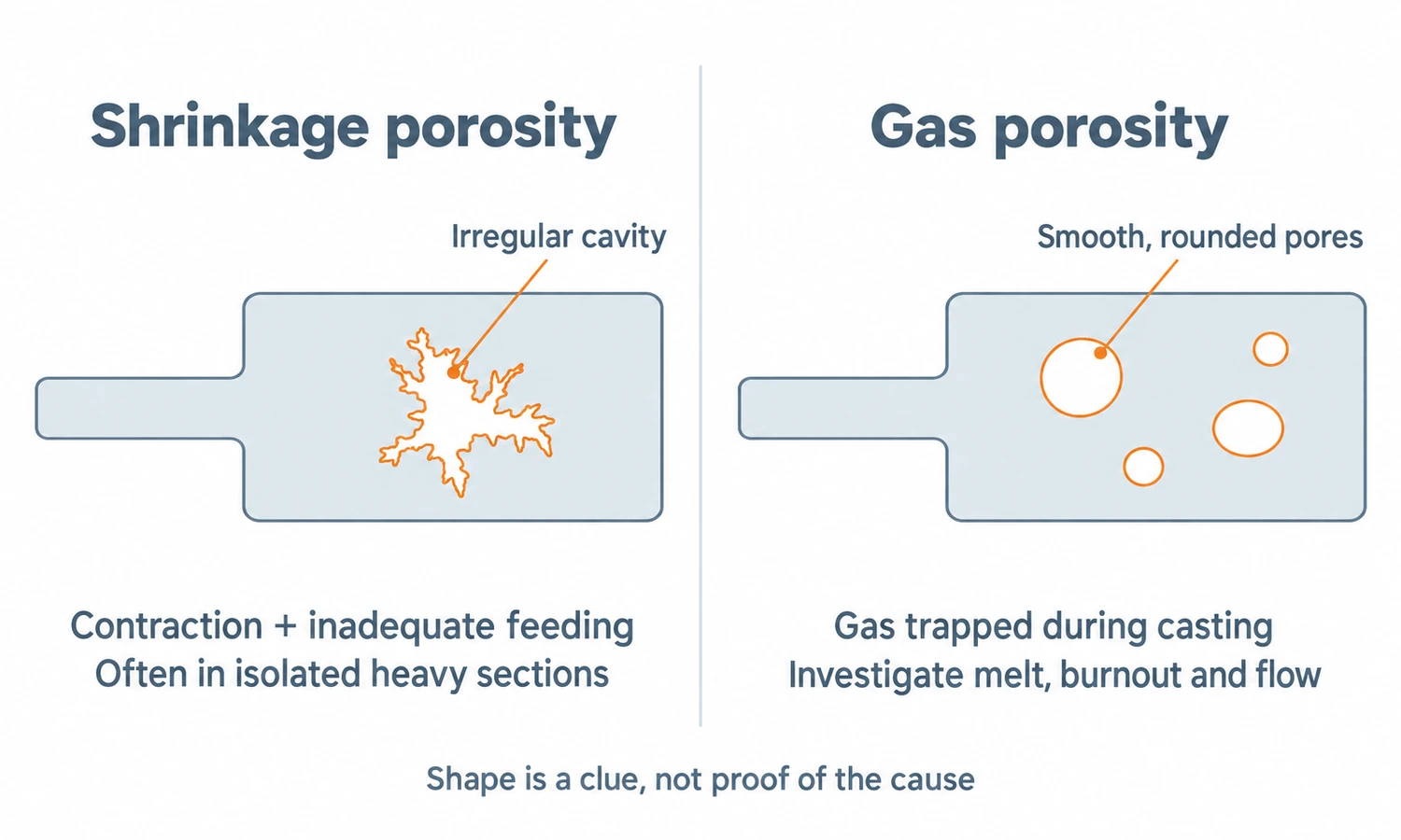
This distinction matters because the corrective actions are different.
Degassing the melt will not solve a feeding problem, while increasing gate size will not remove gas created by incomplete burnout.
In investment casting, the shell once contained wax, so dewaxing and burnout also belong in the investigation when gas defects appear.
Ceramic, Oxide, and Slag Inclusions: Foreign Material in the Casting
An inclusion forms when material other than the intended alloy becomes trapped in or against the casting.
Ceramic inclusions are particularly relevant to investment casting because metal is poured directly into a ceramic shell.
Shell cracking, spalling, loose ceramic near the pouring cup, or poorly finished wax-tree joints can all introduce ceramic material into the mold cavity. ICI’s non-metallic inclusion guidance specifically identifies mold material as one possible source.
This is a good example of a defect whose cause may begin much earlier than pouring.
A rough or poorly sealed wax joint can trap ceramic during shell building. That ceramic may later break loose and appear as an inclusion in the finished casting.
Oxide and slag inclusions originate mainly from the molten metal rather than the shell. Turbulent flow can fold oxide films into the liquid alloy instead of allowing them to remain at the surface.
The defects may look similar, but prevention starts in different parts of the process.
Finning and Excess Metal: Defects Caused by Shell Cracks
Finning appears as a thin metal projection on the casting surface.
The usual mechanism is straightforward: the ceramic shell cracks, molten metal enters the crack, and the metal solidifies there.
ICI notes that shell cracking during drying, handling, or dewaxing can lead to finning.
It is important to distinguish this from wax flash.
Wax flash normally follows the pattern-tool parting line and is reproduced through the ceramic shell. A shell-crack fin may appear in a completely different location.
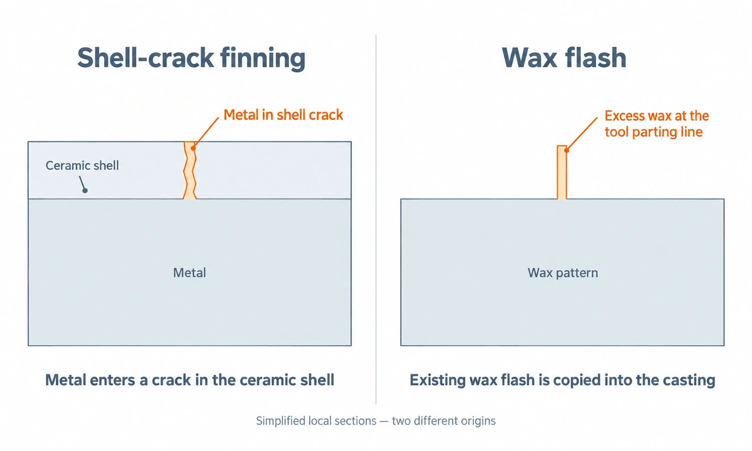
Shell strength, drying, wax expansion during dewaxing, geometry, and local shell thickness all influence the risk.
Our guide to ceramic slurry in investment casting explains why slurry, stucco, drainage, drying, and shell buildup need to work as one system.
Rough Surface and Metal Penetration: Problems at the Wax-Shell-Metal Interface
Investment casting is known for good surface finish, but the final surface passes through several stages before metal is ever poured.
The metal tooling creates the wax surface. The wax pattern creates the shell surface. The shell then becomes the surface against which metal solidifies.
A rough result can therefore begin at any of these stages.
ICI describes penetration as small metal projections that can create a sandpaper-like surface. Poor prime-coat coverage, trapped air, unsuitable slurry condition, or shell-surface problems can contribute.
A rough casting should therefore not automatically be blamed on the ceramic shell.
The wax may already have been rough, the prime coat may not have reproduced it correctly, or later blasting and grinding may have damaged an otherwise acceptable casting.
Hot Tears and Cracks: Identify When the Crack Formed
A hot tear forms while the casting is still weak during late solidification or early cooling.
As metal cools, it contracts. If the geometry, gating system, or surrounding shell prevents that contraction from occurring freely, highly stressed regions can tear.
ICI notes that hot tears often occur near thick-to-thin transitions, slow-cooling regions, or areas where contraction is strongly restrained.
Sharp internal corners and poorly located gates can increase the risk.
But not every crack found on a finished casting is a hot tear.
Cracks can also be introduced later during cut-off, grinding, straightening, heat treatment, or handling.
The important question is therefore not only:
Where is the crack?
It is also:
At what stage did it form?
Changing gating will not solve a crack introduced during aggressive cut-off, just as changing heat treatment will not fix a genuine solidification tear.
Distortion and Dimensional Errors Can Begin Before Metal Is Poured
A casting can fail without containing any visible crack, cavity, or inclusion.
It may simply be the wrong shape.
Long sections, thin walls, asymmetric geometry, and uneven section thicknesses can all make investment castings sensitive to distortion.
Movement can begin in the wax pattern, occur during tree assembly, develop as the metal cools, or appear later during heat treatment and straightening.
ICI’s guidance on casting distortion reflects this multi-stage problem.
A final CMM report only shows that the dimension is wrong. It does not identify when the movement happened.
For sensitive parts, it can therefore be useful to compare wax dimensions, as-cast dimensions, and post-heat-treatment dimensions during process development.
This helps avoid correcting the wrong stage.
For example, changing wax tooling cannot solve a dimension that only moves during quenching.
How Investment Casting Defects Are Detected
Different defects require different inspection methods.
Visual inspection can identify many surface problems such as non-fill, fins, roughness, and obvious cracks. Dimensional inspection detects distortion and tolerance issues.
Liquid penetrant testing can reveal suitable surface-breaking discontinuities that are difficult to see directly.
Radiography is useful for internal volumetric indications such as shrinkage and some forms of gas porosity. CT can provide more detailed three-dimensional information for critical components, although it is not necessary for ordinary production parts.
Pressure or leak testing answers a different question again: whether a component intended to contain fluid or gas actually performs that function.
Inspection should match the risks of the part rather than applying every possible test to every casting.
A Detected Discontinuity Does Not Automatically Mean the Casting Must Be Rejected
Casting inspection is not simply a search for absolute perfection.
A detectable discontinuity may or may not be acceptable depending on its type, size, severity, position, and the requirements of the component.
ASTM E446, for example, provides reference radiographs for steel castings showing different discontinuity types and severity levels. These can be used when purchaser and supplier agree on acceptance criteria.
This prevents two common mistakes.
One is accepting serious internal defects because “some porosity is normal.”
The other is rejecting harmless indications even though no drawing or specification requires that level of soundness.
For critical parts, acceptance criteria should be agreed before production—especially when radiography, penetrant testing, or other NDT is required.
How We Reduce Investment Casting Defects at YTD
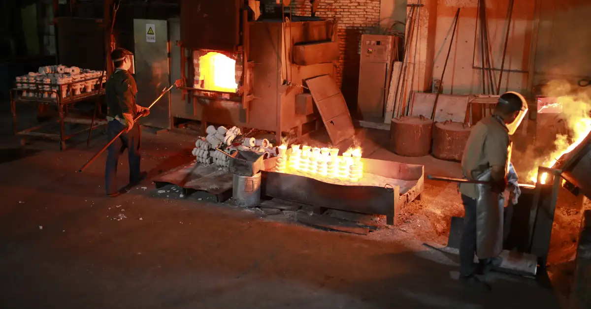
At YTD, defect prevention starts before pouring.
We review geometry, wall-thickness transitions, gating, machining allowance, and areas that may be difficult to fill or feed. For suitable parts, casting simulation helps us evaluate filling and solidification before the production route is finalized.
We also inspect wax patterns before tree assembly so obvious distortion, flash, incomplete filling, or surface damage does not move into shell building.
From there, shell building, melting, pouring, heat treatment, cut-off, machining, and inspection each have their own controls.
The goal is not to claim that defects never occur. It is to understand the realistic risks of each casting, control them as early as possible, and inspect the finished part according to its actual requirements.
Schlussbetrachtung
Investment casting defects become easier to troubleshoot when they are treated as evidence of what happened during the process.
Non-fill points toward filling. Shrinkage points toward feeding and solidification. Rounded pores suggest gas. Fins point toward shell cracking, while dimensional errors may begin in wax or appear much later during heat treatment.
Good defect control means finding the stage where the problem started—not simply naming what the finished casting looks like.
Häufig gestellte Fragen
What Are the Most Common Investment Casting Defects?
Common defects include shrinkage porosity, gas porosity, non-fill, cold shuts, ceramic and oxide inclusions, shell-related fins, rough surfaces, cracks, hot tears, and distortion.
What Causes Porosity in Investment Castings?
Shrinkage porosity forms when solidifying metal cannot receive enough liquid feed metal. Gas porosity forms when gas becomes trapped in the metal. Their appearance and corrective actions are different.
What Causes Ceramic Inclusions?
Ceramic material can enter the cavity when the shell cracks, spalls, or contains loose material. Poor wax-tree joints can also trap ceramic that later breaks loose.
Why Do Investment Castings Have Misruns?
Misruns occur when metal loses the temperature or flow needed to fill the cavity. Thin sections, long flow paths, low metal or shell temperature, and unsuitable gating can contribute.
Can Casting Simulation Eliminate Defects?
No. Simulation can help identify filling, hot-spot, shrinkage, and feeding risks before production, but results still need to be validated with actual castings.
Does Any Porosity Mean the Casting Is Bad?
No. Acceptability depends on the type, severity, location, component function, and agreed specification. Porosity in a critical sealing or highly stressed region may be treated very differently from a small indication in a non-critical area.